

Optimized with highly sensitive cap touch sensors, extensive peripheral circuits and 125℃ operation
How to Calculate Firing Angle of an SCR for AC Voltage Regulator Design
In the field of power electronics, AC Voltage Regulator is a type of power converter that is used to convert a fixed AC voltage into variable AC Voltage. A variable AC power supplies can be used in most of the day to day applications like heaters (for altering temperature settings), Fans, Dimmer Circuits, etc.
For modern-day microcontroller-based Smart Home appliances, understanding the interface between digital electronic to power electronic becomes a necessity, hence this article provides a detailed overview of AC Voltage Regulators and the necessary design parameters.
Different Types of AC Power Controllers
Based on the Controlling parameters, the AC power controllers can be divided into two categories:
- Magnitude Control by controlling the Phase Angle
- Frequency Control with Cycloconverters
Whereas AC Voltage Regulators fall under the phase Angle control category, which provides variable output voltage without any change in Supply Frequency.
Classification of Switching Devices based on Control Methodologies
The Semiconductor devices used in Switched-mode power supplies can be subcategorized into the following three groups, they are Fully Controlled Devices, Fully Uncontrolled Devices, and Partially Controlled Devices. The below table will help you understand the difference between these in brief.
|
Functions |
Fully Controlled Devices |
Fully Uncontrolled Devices |
Partially Controlled Devices |
|
Turn On Control by External Trigger like Gate Pulse |
Yes |
No |
Yes |
|
Turn Off Control by External Trigger like Gate Pulse |
Yes |
No |
No |
|
Example |
An AC sine wave naturally reaches zero voltage for each half cycle and doesn’t require a separate commutation(turn off) circuit. Because of this advantage point, Thyristor family devices are most commonly used for low frequency, high power applications.
The table below describes some key parameters that you will come across while working with Thyristor family devices, it will help you to understand the system better.
|
Parameter |
Definition |
|
Triggering Angle or Firing Angle (α) |
It is the angle at which the SCR gets turned on and starts conducting. This is the angle where the designers apply the gate pulse to control SCR/Thyristor. |
|
Commutation angle or Extinction Angle (β) |
It is the angle at which the SCR gets turned off. For AC Resistive load applications normally, the Commutation takes place at every zero crossings. In RL Load application it will vary irrespective of Zero Crossing |
|
Conduction Angle (γ) |
It is the angle at which the SCR/Thyristor in On State and experience the current flow. |
The below figure shows the output voltage curve where the connected load is purely Resistive. The SCR naturally gets turned off when the Supply voltage reaches zero. The triggering angle, commutation angle, and conduction angle is marked below.
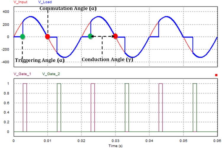
Thyristor Angles for Resistive (R) Load
The above graph shows the input and output response of the AC Voltage Controller with an attached Resistive Load (R). The input supply voltage is shown in Red. The Thyristor is triggered at 50˚ (2.78ms) by applying a pulse to the gate terminal, which is why the output voltage appears suddenly and follows the input voltage. When the input voltage reaches zero at 180˚ (10ms) due to the nature of the sine wave (natural commutation), the Thyristor gets turned off. And the second pulse is applied at 230˚ (12.78ms, but now it’s in the negative half of the sine wave and follows the supply voltage. At 360˚ (20ms), again due to the nature of the sine wave (natural commutation), the thyristor gets turned off still the next pulse is applied.
So, the angles (50˚ and 230˚) is the point in time where we have applied the gate pulse, and the Thyristor starts conducting this is known as the Triggering angle of the SCR. The angles (180˚ and 360˚) where the Thyristors stops conducting and got turned off, called the Commutation angle. The duration where the thyristors (50˚ to 180˚) and (230˚ to 360˚) is in on state (conducting state) where the output load gets powered, is known as the conduction angle.
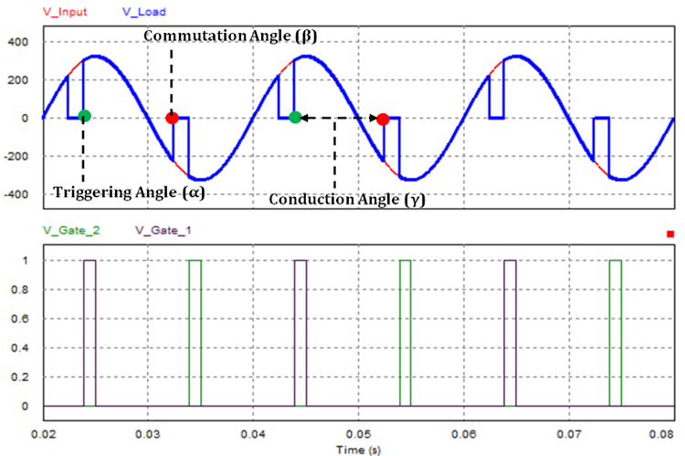
Thyristor Angles for Resistive-Inductive (RL) Load
The above graph shows the output curve when a Resistive and Inductive Load (RL) is attached. With a resistive load, the Thyristors will turn off whenever the input supply voltage crosses zero. But, if we connect an inductive load parallel to the resistive load (like motors) the thyristors will not be able to turn off, even when the input gets to zero. that's due to the nature of the load inductor. So, while using inductive loads like a motor, the next pulse should be applied after the inductor gets fully discharged and the thyristor gets fully turned off.
In the above graph, we applied the triggering pulse at 70˚ and the output voltage follows the input voltage. But at 180˚, the output voltage still follows the negative half cycle instead of turning the gate off. This is because the inductor is discharging, and the power from it prevents the SCR to turn off.
Unidirectional and Bidirectional Control for AC Voltage Regulator
The controlling methods of the AC Voltage Control circuit can be sub-divided into two categories namely Unidirectional Control and Bidirectional Control
The below images will give a basic idea about the unidirectional control method.
Unidirectional Control:
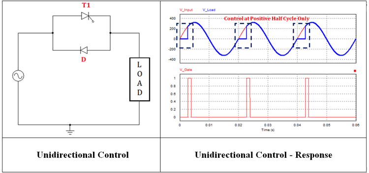
During the positive half cycle of input voltage of the thyristor, T1 starts conducting when the gate triggering signal V_Gate (which is shown in the graph) is applied. When the positive half cycle of input voltage reaches zero due to the natural commutation, the thyristor T1 gets turned off. During the negative half-cycle, the Diode D gets forward biased and starts conducting without any control signal and stops conducting when the negative half cycle reaches zero. With a Unidirectional control mode, one of the half-cycles can only be controlled and the next half-cycle will follow the supply voltage without any control signal. So, the overall controllability of the RMS output voltage is between 70% and 100% only. For the extended control range, we have to go with bidirectional control.
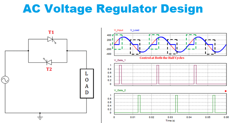
Bidirectional Control:
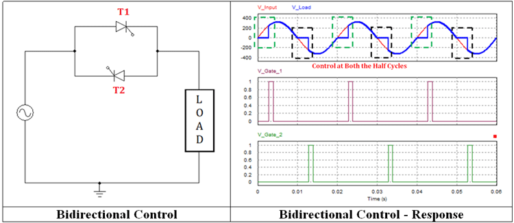
In bidirectional control, the T1 starts conducting during the positive half cycle when the V_Gate_1 pulse triggered T1, and it gets turned off when the supply voltage reaches Zero. During the negative half-cycle, T2 gets triggered by V_Gate_2 pulse and conducts during the remaining half cycle and gets turned off when the negative half cycle reached zero. Thus the bidirectional control provides full controllability during both the half cycles and output can be varied for a wider voltage range.
Practical Implementation of Bidirectional Control
The bidirectional control can be enabled with different configurations based on the device type, no. of devices used, and connection configurations. The below section will give the different types of Bidirectional Control circuits and their pros and cons.
Single SCR with Diode Bridge Configuration for AC Voltage Regulator
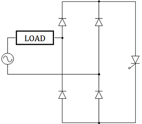
This configuration will need only a single thyristor for bidirectional control since there is a diode bridge involved. It is a simple circuit and can be designed easily as it needs only one control circuit. The downside is it needs a diode bridge which might increase the cost and size of the design.
There’s a lot of ways to archive the AC Voltage Regulation. One way is to include a diode bridge in conjunction with a Thyristor, which converts the bidirectional AC wave to a Unidirectional wave now a single thyristor can control the wave, but another easy method is to use another topology where two SCRs can be used, these two are connected in an inverse parallel configuration and now separately triggering those controls the AC sine wave. A more practical way is to use a TRIAC as this device is made to be triggered bidirectionally, therefore, making them a perfect choice for AC Regulation applications, but that is a topic for another article
I hope you enjoyed the article and learned something new, if you have any questions regarding the topic, feel free to make a comment in the comment section below.


