MEAN WELL Peripheral Accessories are designed to fulfill customers' one-stop shopping requirements.
Understanding High Pass Filters in Electronics: Types, Applications, and Circuit Designs
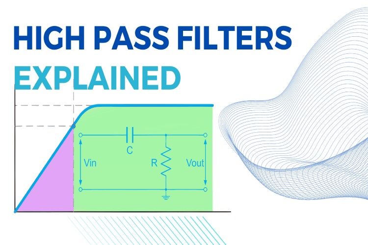
High Pass Filters (HPFs) are crucial components in electronic signal processing, selectively allowing frequencies above a certain threshold to pass while attenuating lower frequencies. Their application spans across various fields, from audio engineering to telecommunications, making them indispensable in modern technology. By definition, a High Pass Filter is an electronic circuit designed to pass high-frequency signals while blocking those of lower frequencies. The key to its functionality lies in its frequency response, particularly the cutoff frequency, which is the threshold below which frequencies are significantly attenuated. High Pass filters have many uses, such as blocking DC component from sensitive devices like radio equipment and such.
Types of High Pass Filters
Based on the circuit construction the High Pass Filters are classified into to two categories, Passive High Pass filters and Active High Pass Filters.
Passive High Pass Filters
As the name suggests these composed of only passive components (R, L, and C). It is constructed using the principle that the reactance of capacitors and inductance components changes with frequency. Passive HPFs are simple in design and do not require external power. Passive filters are highly reliable. The disadvantages of passive filters include passband energy loss, load effect, and EMI if inductive components are used. They function by utilizing the frequency-dependent impedance of capacitors, offering a basic but effective means to filter out lower frequencies. Most common type passive HPFs are RC and LC type. The image below shows the circuit diagram of a simple first order RC HPF.
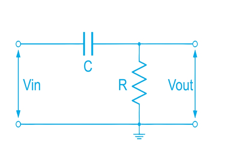
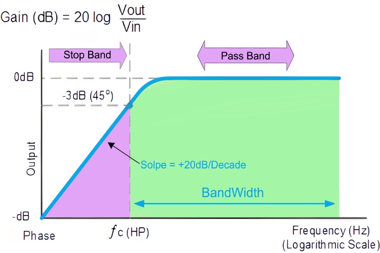
In this circuit, the reactance of capacitor is very high at low frequencies, so the capacitor act as an open circuit, thus blocking the input signal, until the cut of frequency. Above the cut of frequency point the reactance capacitor will be low and it will act as a short circuit, allowing all the input signals, as shown in the frequency response curve shown below.
Active High Pass Filters
Active HPFs incorporate active components like operational amplifiers. They are notable for their amplification capabilities, allowing for greater control over the filter’s gain and enhanced performance in specific applications. The main advantages of active High Pass Filters include no passband energy loss, possible amplification, no load effect, easy to cascade to form high order filters. In addition, Active HPFs are small in size, light weight and doesn’t cause any EMI. The disadvantages of active HPFs includes, it requires external DC power supply, passband range is limited by the bandwidth of active devices such as operational amplifiers. Thus, makes it not suitable for high-voltage, high-frequency and high-power applications.
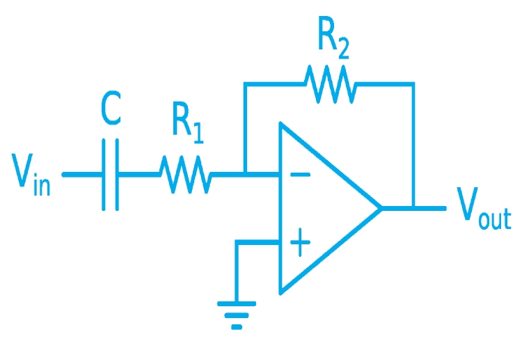
The above image shows an active electronic implementation of a first-order high-pass filter using an operational amplifier. Its cut of frequency of first order RC high pass filters can be calculated using the following equation: f_c=1/(2πR_1 C)
Orders of High Pass Filters
According to the mathematical characteristics of the filter, it is divided into the first-order high-pass filter, second-order high-pass filter, etc.
First Order High Pass Filters
1st order HPFs, typically designed using RC circuits, exhibit a frequency response with a linear slope of 20 dB per decade. They are straightforward to implement and offer a gentle roll-off in frequency response. The circuit explained in the passive filter section is a 1st order RC high pass filter.
Cut of frequency of first order RC high pass filters can be calculated using the following equation: f_c=1/2πRC
Second Order High Pass Filters
These filters are constructed using cascading two first order filters. They are characterized by a steeper cutoff slope, at 40 dB per decade, offering more precision in filtering out undesired frequencies. The image below shows a 2nd order RC high pass filter. As you can see it made by cascading two first order high pass filters together.
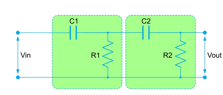
The cut of frequency of second order RC high pass filters can be calculated using the following equation: f_c=1/(2π√(R_1 C_1 R_2 C_2 ))
In practice, cascaded passive filters produce together because the dynamic impedance of each filter order affects its adjacent network, so it is difficult to accurately implement a larger order filter. To mitigate the impact on load, it is feasible to establish a protocol where the impedance of each successive stage is tenfold that of its predecessor. By adopting this approach, setting R2 as 10 times R1 and C2 as 1/10th of C1 facilitates load reduction while preserving filter integrity.