

Optimized with highly sensitive cap touch sensors, extensive peripheral circuits and 125℃ operation
Leakage Current in TRIAC and How to Minimize It
A TRIAC is an electronic component that is widely used to control AC power. Unlike SCR, they can easily switch and control both parts of the AC waveform. This makes this component suitable for a variety of applications where AC power control is needed. An example application would be a dimmer circuit, domestically we use it as a ceiling fan regulator circuit. They can be utilized to control the input power of a motor or electric heater.
This is why TRIAC is used for low to medium power applications leaving the High-power applications to SCR. Although this is a very interesting device, there resides an issue known as “Leakage Current”. And in this article, we will talk all about this leakage current, its adverse effects, and some well-known solutions to resolve these issues. But before that, let's clear out the basics of TRIAC.
Understanding the TRIAC and its Symbol
Like every other electronic component, TRIAC has its own circuit symbols, it comprises two SCRs connected in an antiparallel configure, if we look at its symbol very closely, it clearly represents the bidirectional properties of the TRIAC. Which you observe from the below image.
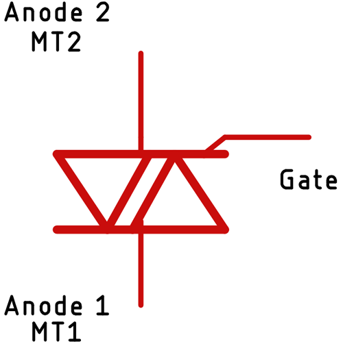
The TRIAC is an upgraded version of the Thyristor. As you already know by now, a thyristor can control current only in one direction, but a TRIAC can control the current for both the negative and positive directions. Because of the nature of the sine wave, TRIAC switches in every cycle of the sine wave, which means, unlike SCRs, we can utilize the full cycle. Like Thyristor, a TRIAC has three terminals, however assigning names to these terminals becomes a bit difficult, because simply the cathode and the anode of two SCRs are connected. Also, the gate terminal of two SCRs is connected, which is why this was named Anode 1 and Anode 2 or Main Terminal 1 and Main Terminal 2 (MT1 and MT2).
How does a TRIAC Work?
Before proceeding further, let’s gain a little bit of knowledge on how a TRIAC works. As you can see from the following picture.
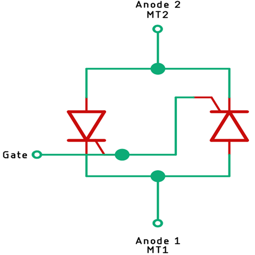
We have said earlier that a TRIAC can be realized as a configuration of two SCRs. The above image gives a little bit more clarity on the topic, but the operation at the semiconductor level is much more complex. Unlike SCR, a TRIAC can be triggered in several ways, it can be triggered irrespective of the polarity of the terminals. It can also be triggered irrespective of the polarity of the triggering pulse. One thing to note while working with TRIAC is that the sensitivity of the trigger current is much greater when the MT2 and gate current are in the same polarity. Now with the basic cleared out, we can move on to clearing out our main problem of leakage current.
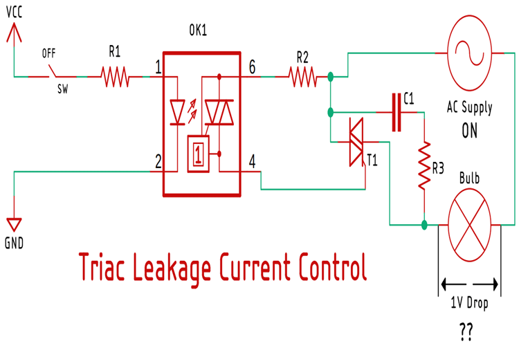
What is Leakage Current and How Can we Minimize It?
Thyristor, TRIAC, or any other solid-state AC switches have structural leakage current in the off state, which is why a small amount of current flows through the load, in some cases, this circuit is enough to charge a load circuit (Inductive) and causes it to spontaneously flash. To prevent this, we need to take good care of the specifics and design the circuit accordingly, and in this section of this article, we will talk more about it.
If the Main Terminal 2 (MT2) voltage exceeds a certain rated threshold voltage (can occur because of high voltage transients condition), the leakage current between two terminals will reach a point where the TRIAC will break into conduction mode. In this state, if a sudden increase in current flows through the TRIAC, a sudden localized heat will be generated, because of which the TRIAC can get destroyed. Incandescent lamps, capacitive loads are most likely the cause of high inrush currents.
This situation can be avoided by applying one or more of the following solutions:
- Ensuring the Temperature does not exceed given Maximum Temperature Ratings Tj max. As temperature increases, the leakage current through the device increases, we can eliminate/reduce this problem by incorporating specific brands of TRIAC for specific requirements.
- We can reduce the sensitivity of the TRIAC by putting a large value resistor from the gate to the cathode. This will reduce the gate current thus reducing the leakage current. On the other hand, it increases the turn-on time of the TRIAC.
- If the above-mentioned methods are not possible to apply, we can use a TRIAC with a less sensitive gate and apply a small degree of reverse biasing to the gate during the off period. In this method, we have to minimize the power dissipation through the gate.
- Another method to minimize leakage current is to completely remove the snubber circuit, depending on the type of load. Often the capacitor leakage becomes the main source of leakage current, so by eliminating the snubber network, we can reduce the current flow through the snubber and reduce the leakage current.
I hope you enjoyed the article and learned something new, if you have any other questions regarding the topic, please leave a comment down below.


