BT134 Sensitive Gate TRIAC Pinout, Specifications & Datasheet
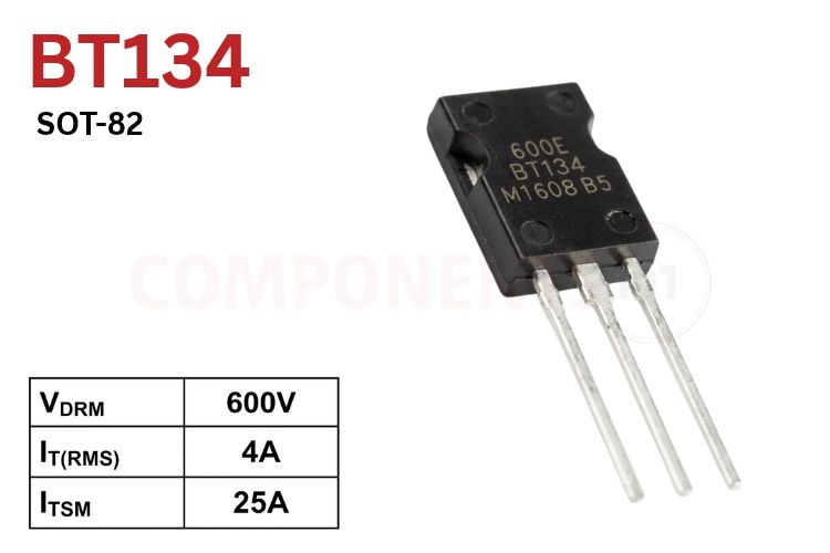
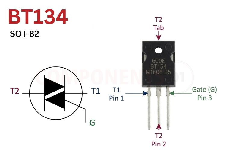
BT134 Pinout Configuration
Holding the BT134 in its SOT-82 package with the marked front face toward you and the three leads pointing downward, the terminal connections from left to right are listed below.
| Pin Number | Pin Name | Terminal Type | Description |
| 1 | T1 (MT1) | Main Terminal 1 | First main power terminal; acts as the reference point for Gate trigger voltage and current |
| 2 | T2 (MT2) | Main Terminal 2 | Second main power terminal; typically connected to the AC load side |
| 3 | G | Gate | Trigger input; applying a small positive or negative pulse relative to T1 turns on the TRIAC |
| Tab / Base | T2 (MT2) | Non-Isolated Metal Base | Exposed rear mounting base internally shorted to Pin 2 (T2); insulate before bolting to a grounded heatsink |
BT134 Series Voltage Variants
The NXP / Philips BT134 series E family shares the same 4A RMS current capability and sensitive-gate specification across three peak repetitive off-state voltage (VDRM) grades.
| Part Number | Repetitive Peak Off-State Voltage (VDRM) | RMS On-State Current (IT(RMS)) |
| BT134-500E | 500V | 4A (Tmb ≤ 107°C) |
| BT134-600E | 600V | 4A (Tmb ≤ 107°C) |
| BT134-800E | 800V | 4A (Tmb ≤ 107°C) |
BT134 Key Features & Specifications
- Device Category: 4-Quadrant Sensitive-Gate Bidirectional TRIAC
- Package Type: SOT-82 Plastic Envelope (Net Mass: 0.8 g)
- Repetitive Peak Off-State Voltage (VDRM): 500V (BT134-500E), 600V (BT134-600E), 800V (BT134-800E)
- RMS On-State Current (IT(RMS)): 4A max (full sine wave, Tmb ≤ 107°C)
- Non-Repetitive Peak Surge Current (ITSM): 25A (t = 20 ms, 50 Hz) / 27A (t = 16.7 ms, 60 Hz)
- Fusing Value (I²t): 3.1 A²s (t = 10 ms)
- Gate Trigger Voltage (VGT): 0.7V typ, 1.5V max (Tj = 25°C); 0.25V min (VD = 400V, Tj = 125°C)
- Holding Current (IH) & Latching Current (IL): IH = 2.2 mA typ (15 mA max); IL = 15 mA max (Q1, Q3) / 20 mA max (Q2, Q4)
- On-State Voltage Drop (VT): 1.4V typ, 1.70V max (IT = 5A)
- Critical Rate of Rise of Off-State Voltage (dVD/dt): 50 V/µs typ (VDM = 67% VDRM(max), Tj = 125°C, gate open)
- Critical Rate of Rise of On-State Current (dIT/dt): 50 A/µs (T2+ G+, T2+ G-, T2- G-); 10 A/µs (T2- G+)
- Peak Gate Limits: IGM = 2A, VGM = 5V, PGM = 5W, PG(AV) = 0.5W
*Note: Complete Technical Details can be found in the BT134 datasheet given at the end of this page.
BT134 Equivalent & Alternative Components
Depending on your package preference (SOT-82 vs TO-220 vs TO-92), current budget, or gate-sensitivity requirements, these TRIACs serve as close equivalents or upgrade paths.
| Part Number | Key Ratings (VDRM / IT(RMS) / IGT) | Package & Remarks |
| BT136-600E | 600V, 4A, 10 mA (Q1-Q3) | Larger TO-220AB equivalent with lower thermal resistance for heatsink mounting |
| BT139-600E | 600V, 16A, 10 mA (Q1-Q3) | High-current TO-220 sensitive-gate upgrade for heavy heaters and motors |
| BT131-600 | 600V, 1A, 3-7 mA | Smaller TO-92 sensitive-gate TRIAC for sub-1A pilot loads and indicator lamps |
| Z0409MF | 600V, 4A, 10 mA | Direct SOT-223 / TO-202 / IPak sensitive-gate 4A TRIAC family alternative |
| BTA06-600C | 600V, 6A, 25 mA | Insulated-tab TO-220AB alternative when heatsink electrical isolation is required |
Brief Description of BT134
High Gate Sensitivity Across All Four Quadrants: Because the BT134 series E guarantees IGT ≤ 10 mA in Quadrants I, II, and III (and ≤ 25 mA in Quadrant IV), it latches reliably with modest gate currents, making it ideal for compact AC solid-state relays and direct coupling to phototriac optocouplers.
Noise Immunity & Inductive Snubbing (dVD/dt = 50 V/µs): High gate sensitivity naturally lowers critical off-state dVD/dt immunity compared to heavy snubberless TRIACs. When switching inductive motors, solenoid valves, or transformers or on electrically noisy AC mains, connect an external RC snubber across T1 and T2 and keep a 1 kΩ bleed resistor between Gate and T1.
BT134 Datasheet
Download BT134 Series E Sensitive-Gate TRIAC Datasheet PDF (NXP Semiconductors)
Applications
- Domestic AC ceiling fan speed regulators and incandescent/halogen lamp dimmers
- Compact microcontroller-controlled solid-state relays (SSRs) for smart home switches
- Small AC motor drives, aquarium pumps, and sewing machine speed pedals
- Coffee makers, soldering iron temperature controllers, and appliance heater switches
- Automated AC solenoid valves and Christmas/architectural lighting sequencers
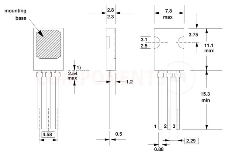
2D Model and Component Dimensions
All physical outline dimensions below correspond to the NXP SOT-82 plastic package drawing (all measurements in millimetres, mm; net weight 0.8 g).
| Dimension Parameter | Nominal / Limit (mm) | Notes |
| Package Body Width | 7.8 max | Front face width across plastic body |
| Package Body Height | 11.1 max | Molded plastic body height |
| Package Thickness | 2.3 – 2.8 | Front-to-back mold depth |
| Mounting Base Offset from Top | 3.75 | Centerline distance from top edge |
| Side Mounting Recess Diameter | 2.5 - 3.1 | Dual semi-circular clamp/screw notches |
| Lead Length | 15.3 min | Minimum terminal length below mold body |
| Adjacent Pin Pitch | 2.29 | Center spacing between Pins 1–2 and 2–3 |
| Outer Pin Span (Pin 1 to Pin 3) | 4.58 | Total span between outer terminal centers |
| Lead Width / Thickness | 0.88 max / 0.5 | Terminal width and stamped metal thickness |