TIP31C – NPN Power Transistor

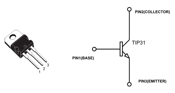
TIP31C Pin Configuration
TIP31C is a NPN POWER TRANSISTOR. Like any other transistor, it has three pins namely EMITTER, BASE, and COLLECTOR. The pin configuration of TIP31C is given below.
|
Pin Number |
Pin Name |
Description |
|
3 |
Emitter (E) |
Normally connected to GROUND |
|
2 |
Collector (C) |
Normally connected to LOAD |
|
1 |
Base (B) |
Normally used as TRIGGER to turn ON the TRANSISTOR. |
TIP31C Features and Specifications
- Medium power TRANSISTOR
- With hfe gain up to 50
- With hfe improved linearity
- Maximum voltage across COLLECTOR and EMITTER of TRANSISTOR: 100V
- Maximum current allowed trough TRANSISTOR COLLECTOR: 3A DC
- Maximum voltage across BASE and EMITTER of TRANSISTOR:5 V
- Maximum current allowed trough TRANSISTOR BASE: 1A DC
- Maximum voltage across COLLECTOR and BASE of TRANSISTOR: 100V
- Maximum operating Temperature: 150ºC
Note: Complete technical information can be found in the TIP31C Transistor Datasheet linked at the bottom of this page.
TIP31C Equivalents
TIP31C TRANSISTOR has many replacements like TIP31A, 2N6122, TIP31B, MJE340K, SW4F013. We need to check parameters and Pin configuration carefully before replacing. Replacing without considering voltage, current and gain parameters may lead to permanent damage.
Similar to TIP31C
TIP122, TIP121, TIP120, 2N6288, 2N6290, 2N6292
Where to Use TIP31C
For understanding the use of TIP31C, consider:
Case1: When you want a simple SWITCHING device for MEDIUM POWER LOADS. TIP31C is one of the basic TRANSISTORS out there which are easily available and cheap. With electrical characteristics suiting many applications it is fairly popular. So the component is best suited when choosing a random switching device.
Case2: When you want AMPLIFY a signal. The amplifying factor of TIP31C is fairly good and the important thing is gain is almost linear. So these characteristics make TIP31C one of best contender for amplifying applications.
Case3: TIP31C can be controlled by MICROCONTROLLER pulses because of its gain and high speed response. So it can be used in high speed switching applications.
How to use TIP31C
TIP31C can be used like any other power TRANSISTOR. Here we are going to use TIP31C in COMMON EMITTER configuration to understand its working.
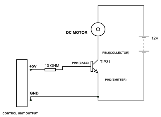
In the circuit above, we are using TIP31C as a simple switching device. As show in figure, we are using a small DC MOTOR as the LOAD. The TRIGGER for turning ON the TRANSISTOR is provided by CONTROL UNIT (NOT MICROCONTROLLER as MICROCONTROLLER cannot deliver 300mA). The control unit provides +5V pulses to base of TRANSISTOR. The CONTROL UNIT GROUND must be connected to TRANSISTOR EMITTER compulsorily.
The 10Ω resistor is provided for limiting the current through BASE. This BASE current limiting resistor is important. Could be chosen accurately by calculating:
Maximum current through BASE = 1 Amp
Choose BASE current = 0.9 Amp
Maximum Voltage across BASE and EMITTER= 5 Volt
Choose Vbe = 4.5
Voltage across resistor R = CONTROL UNIT VOLTAGE OUTPUT – 4.5 = XX V
Resistor R = XX/0.9 = YYΩ.
Put YY Ω resistance in series with base as shown in circuit.
Under normal conditions, the TRANSISTOR will be OFF as these will be no BASE current. When the CONTROL UNIT voltage pulses reaches BASE then current flows through BASE of TRANSISTOR. With BASE current flow, TRANSISTOR gets turned ON. With that there will be COLLECTOR current which flows through MOTOR. So the MOTOR rotates. The MOTOR will be keep rotating until there will be BASE current.
When the CONTROL UNIT output goes LOW the BASE current becomes ZERO. The TRANSISTOR gets turned OFF when the BASE current becomes ZERO. So the COLLECTOR current also becomes ZERO, bringing MOTOR to STOP.
This way we can use TIP31C as a switching device. The circuit used above is a simple testing circuit and is not an application circuit. Using it without arrangements like HEAK SINK, FLYBACK DIODE, etc. will damage the device.
For using the TIP31C as an amplifier one needs to consider current gain characteristics. So we will introduce the CURRENT GAIN graph of TIP31C for better understanding. The typical DC GAIN graph of TIP31C is given below.
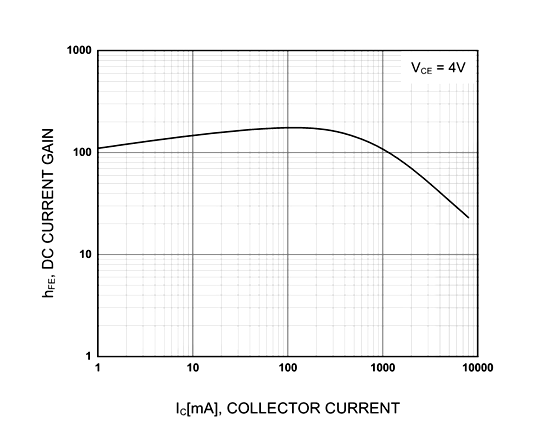
From graph the GAIN is almost 100 when COLLECTOR current is 1000mA or 1A. And GAIN drops to 60 when COLLECTOR current is 2000mA or 2A. When COLLECTOR current goes beyond 2A the GAIN is almost linear. This parameter value is important for APLIFIERS. By taking these ranges into consideration we can make appropriate arrangements for better performance.
Applications
- DC motor speed control
- Lighting systems
- PWM applications
- Relay drivers
- Switch mode power supply
- Audio Amplifiers
- Signal Amplifiers
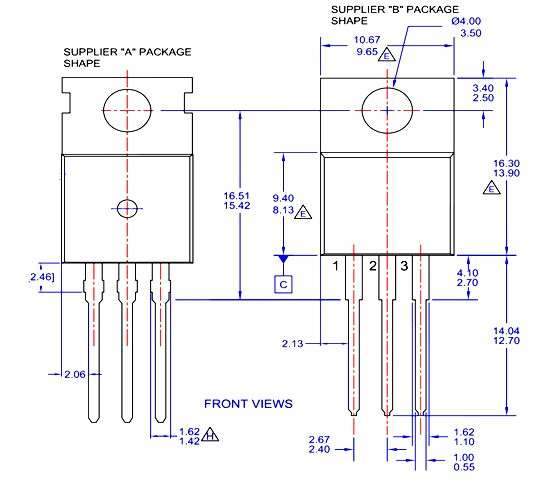
2D-Model and Dimensions
All measurements are in millimeters