TIP122 - Darlington NPN Transistor
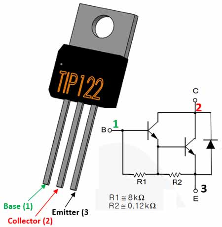
TIP122 Transistor Pinout Configuration
|
Pin Number |
Pin Name |
Description |
|
1 |
Base |
Controls the biasing of transistor, Used to turn ON or OFF the transistor |
|
2 |
Collector |
Current flows in through collector, normally connected to load |
|
3 |
Emitter |
Current Drains out through emitter, normally connected to ground |
Features
- Darlington Medium-power NPN Transistor
- High DC Current Gain (hFE), typically 1000
- Continuous Collector current (IC) is 5A
- Collector-Emitter voltage (VCE) is 100 V
- Collector-Base voltage (VCB) is 100V
- Emitter Base Voltage (VBE) is 5V
- Base Current(IB) is 120mA
- Available in To-220 Package
Note: Complete Technical Details can be found at the TIP122 datasheet given at the end of this page.
Alternative NPN Transistors:
BC549, BC636, BC639, BC547, 2N2369, 2N3055, 2N3904, 2N3906, 2SC5200
TIP122 Equivalent Transistors:
TIP127 (PNP), 2N6045, 2N6532, 2SD1415, 2SD2495, BDT63, BDW2, KSB601, KSD560, MJF6388
Same Family Transistors:
TIP120, TIP121, TIP122 (NPN); TIP125, TIP126, TIP127 (PNP)
About TIP122:
The TIP122 is a Darlington pair NPN transistor. It functions like a normal NPN transistor, but since it has a Darlington pair inside it has a good collector current rating of about 5A and a gain of about 1000. It can also withstand about 100V across its collector- Emitter hence can be used to drive heavy loads. The Darlington pair inside this transistor is shown clearly as its internal circuit schematic below
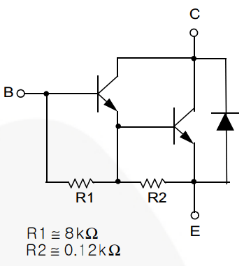
As you can see, there are two transistors inside this TO-220 package in which the emitter of the first transistor is connected with the base of the second transistor and the collector of both transistors are connected together to form a Darlington pair. This increases the current gain and current rating of this transistor.
Where to TIP122:
This transistor is known for its high current gain (hfe = 1000) and high collector current (IC =5A) hence it is normally used to control loads with high current or in applications where high amplification is required. This transistor has a low Base-Emitter Voltage of the only 5V hence can be easily controlled by a Logic device like microcontrollers. Although care has to be taken to check if the logic device can source up to 120mA.
So, if you looking for a transistor that could be easily controlled by a Logic device to switch high power loads or to amplify high current then this Transistor might be an ideal choice for your application.
How to use TIP122:
Although TIP has high collector current and current gain, it is fairly simple to control the device since it has an Emitter-Base voltage (VBE) of only 5V and base current of only 120mA. In the below circuit I have used the TIP122 to control a 48V motor which has a continuous current of about 3A.
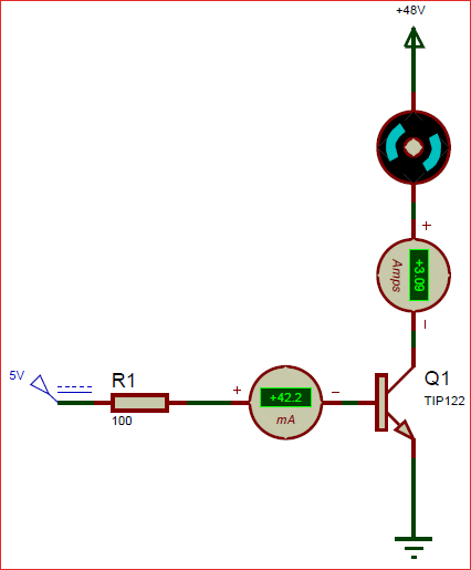
The continues collector current of this transistor is 5A and our load consumes only 3A which is fine. The maximum base current is about 120mA, but I have used high value of 100ohm resistor to limit it to 42mA. You can use even a 1K resistor if your collector current requirement is less. The peak (pulse) current of this transistor is 8A so make sure your motor does not consume more than that. This is just a model circuit diagram that shows the working on this transistor it cannot be used as such. So, similarly you can control your load in the same way.
Applications
- Can be used to switch high current (upto 5A) loads
- Can be used as medium Power switches
- Used where high amplification is needed
- Speed control of Motors
- Inverter and other rectifier circuits
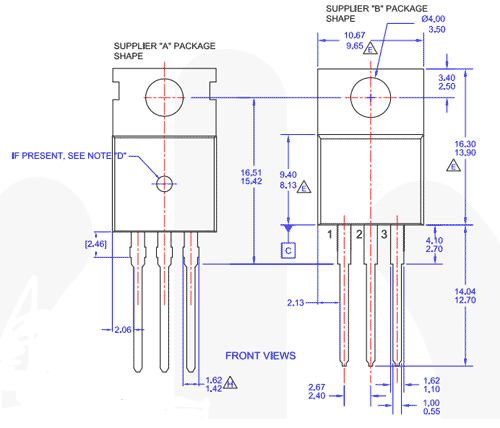
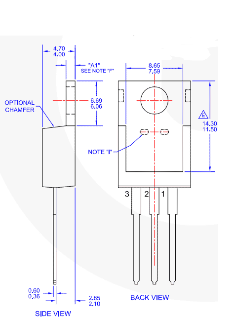
2D-Model
2D dimensions will help you in placing this component at the time of making circuit on perf board or a PCB.
