2N3055 – NPN Power Transistor

2N3055 is a general purpose NPN power transistor manufactured with the epitaxial base process, mounted in a hermetically sealed metal case. The device is designed for general purpose switching and amplifier applications.
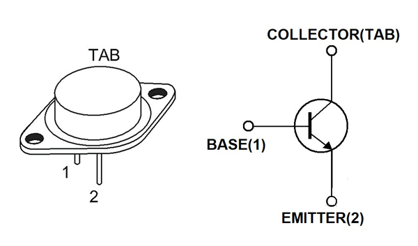
2N3055 Pin Configuration
Like any other transistor 2N3055 has three pins namely EMITTER, BASE and COLLECTOR. The pin configuration of 2N3055 is given below.
|
Pin Number |
Pin Name |
Description |
|
1 |
Base (B) |
Normally used as trigger to turn ON the transistor |
|
2 |
Emitter (E) |
Normally connected to GROUND |
|
TAB or CASE |
Collector (C) |
Normally connected to LOAD |
2N3055 Features and Specifications
- Medium power transistor
- Excellent safe operating area
- Complementary NPN - PNP transistors
- Low collector-emitter saturation voltage
- Pb−free packages are available
- DC current gain (hFE) up to 70
- With
- Maximum voltage across collector and emitter: 60V DC
- Maximum current allowed trough collector: 15A DC
- Maximum voltage across base and emitter: 7V DC
- Maximum current allowed through base: 7A DC
- Maximum voltage across collector and base: 100V DC
- Operating temperature range: -65ºC to +200ºC
- Total power dissipation: 115W
2N3055 Equivalents
2N6673, 2N6675, complementary pair- MJ2955
Similar Transistors
MJ10023, BUX98, BDW51
2N3055 Transistor Overview
2N3055 is preferred when you want a simple switching device for medium power loads. 2N3055 is one of the basic transistors available in the market for cheap and with features being suited for many applications.
2N3055 is also used in audio power amplifiers. The device has good amplifying factor and also the gain is almost linear making 2N3055 one of best solution for power amplifiers.
How to use 2N3055 Transistor
As mentioned earlier the 2N3055 can be used for any NPN transistor applications but for understanding the functioning of device let us consider a simple application circuit as shown below. Here we are going to use 2N3055 as a simple switching device to drive a motor and is in common emitter configuration.
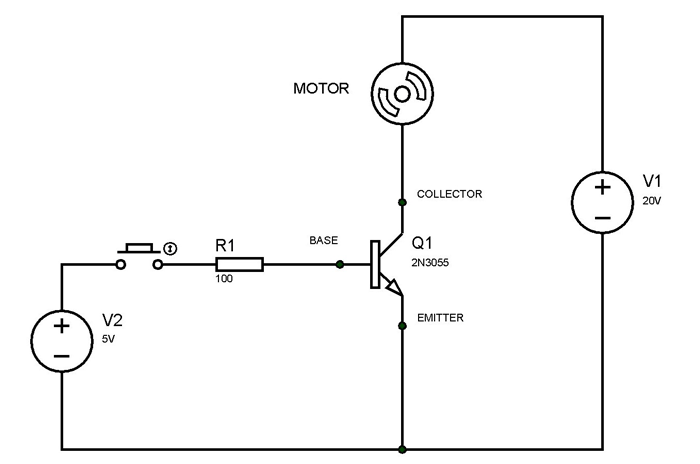
As show in circuit we are using a motor as the load and the gate signal for turning ON the transistor is provided by 5V source with button being the triggering device. The trigger source and power source must share a common ground for the circuit to work. The 100Ω resistor is provided for limiting the current through base.
Under initial conditions the button will be open and no current flows through the base of transistor. With no base current the transistor acts as open circuit and the entire supply voltage V1 will appears across it.
When the button is pressed at certain time, the voltage V2 forms a closed loop with base-emitter of transistor as can be seen in circuit diagram. With this closed loop a current flows through base of transistor and with base current flow the transistor gets turned ON. Having transistor acting as short circuit in ON state there will be collector current which flows through motor making it rotate. This motor will keep rotating until there will be base current.
After a certain time when the button is released the base current becomes zero and the transistor gets turned OFF. With transistor going to high resistance state in OFF mode, the collector current also becomes zero bringing motor to stop.
The way of controlling power motor via simple push button realizes the use 2N3055 as a switching device and in the same way we can use 2N3055 in other transistor circuits.
Applications
- Power switching circuits
- Amplifier circuits
- PWM applications
- Regulator circuits
- Switch mode power supply
- Signal Amplifiers
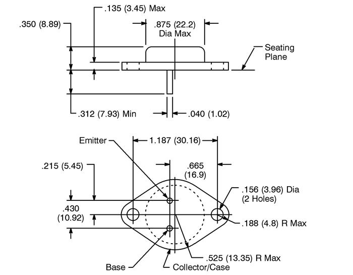
2D-Model
All measurements are in inches and measurements in brackets are scaled in millimeters