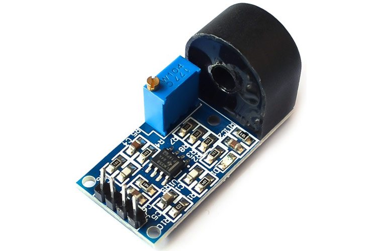
ZMCT103C - Precision Current Sensor
Description of ZMCT103C Current Sensor Module
The microcurrent precision current sensor is a module capable to measure a current level up to 5A. This current sensor module is based upon the ZMCT103C IC. The module has 4 output pins and provides an analog output corresponding to the AC current passing through the wire.
Features of ZMCT103C Current Sensor Module
ZMCT103C is a small size, high accuracy module with some features and specifications mentioned below:
- Current Ratio: 5 A:5 mA
- Rated Primary Current at 50/60 Hz: 5 A
- Winding D.C. Resistance at 20 °C: 155 Ω
- Maximum Primary Current at 50/60 Hz: 20 A
- Transformer Turns Ratio: Np:Ns = 1000:1
- Isolation Voltage: 4500V
- Onboard sampling resistor, to drop the voltage to lower levels
- Operating Temperature: -40 to 85 °C
- Pin Length of the secondary coil (encapsulation) > 3mm
- Epoxy Encapsulation
Pin Configuration for ZMCT103C Current Sensor Module
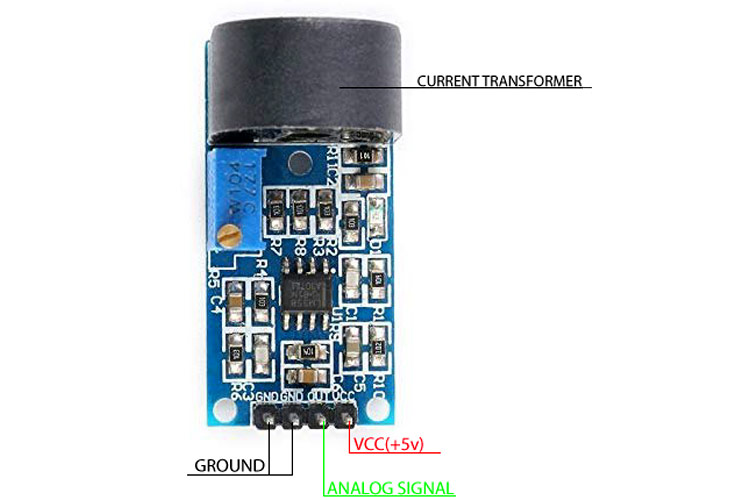
The ZMCT103C module has 4 pins, which are as follows:
- Ground (G)
- Ground(G)
- Signal Out
- VCC(+5V)
Alternatives for ZMCT103C
GY712, ACS712, ACHS 7123, WCS1700, CJMCU 219
Note: All above mentioned modules are current sensors with different current measuring capabilities.
Note: More technical information can be found in the ZMCT103C Datasheet linked at the bottom of this page.
Working of a Current Sensor
Current sensors operate on the principle of variation of magnetic field change between two coils. It generates highly accurate, low noise output voltage signals which are proportional to the applied AC current.
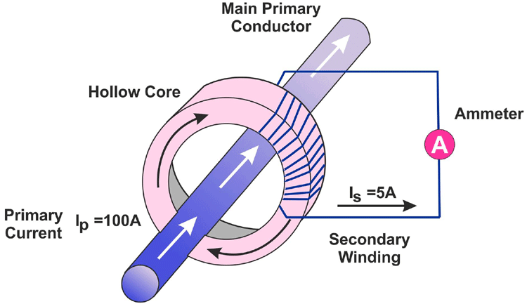
The module is in a donut shape which has an epoxy encapsulation, inside which a secondary coil(Ns) is coiled around a ferrite bead. The wire whose current has to be measured is passed through the donut hole and the wire then acts as a primary coil and the change in the magnetic field results in the desired outputs. The measurement accuracy of the device can be improved by increasing the number of turns in the primary coil. This current transformer comes in use for multiple applications including HEV inverters, Electronic power steering systems, detecting circuit overload, load drop, and shutdown.
Connecting ZMCT103C Current Sensor Module with MCU/MPU
The ZMCT103 current sensor module can be connected to a microcontroller or a processor easily. The module has 4 output pins, two of which are to be shorted. The output pins are as follows; VCC, Ground, Analog Output.
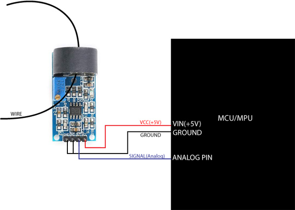
There are two grounds in the current sensor module which are to be shorted and connected to the ground of the MCU. The VCC pin is connected to the 5V of the MCU and the OUT pin on the module is to be connected to the Analog input pin of the MCU/MPU. Once the connections are completed, the wire whose current has to be measured is to be passed through the donut-shaped ZMCT103C IC as shown in the image above.
Module Configuration of a ZMCT103C Current Sensor
The ZMCT103C current sensor module consists of the donut-shaped IC which houses the secondary windings and acts as a transformer for current measurement, as discussed above in the ‘working section’. The module also consists of an OP07 operational amplifier which is connected along with a sampling resistor.
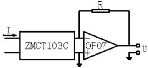
This is a basic circuitry used with the sensor, generally used to amplify the signals generated by the current transformer module.
Note: There is also a potentiometer on the ZMCT103C current sensor module which can be used to adjust the amplification factor.
Applications of ZMCT103C Current Sensor Module
Below are some of the applications of the ZMCT103C current sensor module:
- Measuring AC currents
- Monitor any current surges
- Ground fault detection
- Household electrical equipment
2D Model of ZMCT103C
The 2D model of the current sensor module is shown in the image below. The dimension values can be used to design custom footprints of the module and.
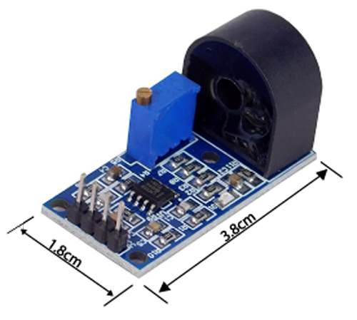
Note: The dimensions are in centimeters.

