ACS712 Current Sensor Module
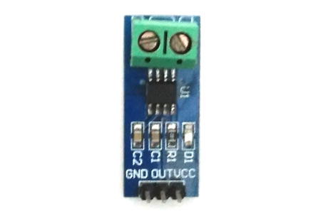
Pin Configuration
|
Pin Number |
Pin Name |
Description |
|
1 |
Vcc |
Input voltage is +5V for typical applications |
|
2 |
Output |
Outputs Analog voltage proportional to current |
|
3 |
Ground |
Connected to ground of circuit |
|
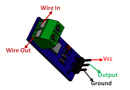
T1 |
Wire In |
The wire through current has to be measured is connected here
|
|
T2 |
Wire Out |
Specifications
- Measures both AC and DC current
- Available as 5A, 20A and 30A module
- Provides isolation from the load
- Easy to integrate with MCU, since it outputs analog voltage
- Scale Factor
|
5A Module |
20A Module |
30A Module |
|
185mV/Amp |
100mV/Amp |
66mV per Amp |
Note: Complete technical information can be found in the ACS712 Datasheet linked at the bottom of this page.
Other current Sensors
ACS759, WCS1700, KG190, ACS715
Where to use ACS712 Module
The ACS712 Module uses the famous ACS712 IC to measure current using the Hall Effect principle. The module gets its name from the IC (ACS712) used in the module, so for you final products use the IC directly instead of the module.
These ACS712 module can measure current AC or DC current ranging from +5A to -5A, +20A to -20A and +30A to -30A. You have to select the right range for your project since you have to trade off accuracy for higher range modules. This modules outputs Analog voltage (0-5V) based on the current flowing through the wire; hence it is very easy to interface this module with any microcontroller. So if you are looking for a module to measure current using a microcontroller for you project, then this module might be the right choice for you.
How to use the ACS712 Module
As told earlier it is very simple to interface the ACS712 Module with Microcontrollers. The below diagram would be more illustrative
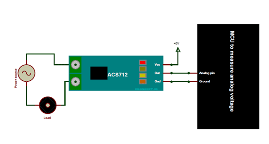
The ACS712 module has two phoenix terminal connectors (green colour ones) with mounting screws as shown above. These are the terminals through which the wire has to be passed. In our case I am measuring the current drawn by the motor so the wires that is going to the load (motor) is passed through the ACS 712 Module. Make sure the module is connected in series with the load and be extra cautious to avoid shorts.
On the other side we have three pins. The Vcc is connected to +5V to power the module and the ground is connected to the ground of the MCU (system). Then the analog voltage given out by the ACS712 module is read using any analog pin on the Microcontroller.
Programming for ACS712 Module
There are few things to know before we could program our Microcontrollers to read current from ACS712 Module. By default when no current is flowing through the module terminals the output voltage will be +2.5V (Vcc/2), when the current flows in one direction the value will increase from 2.5V and when it flows in other direction the values will decrease from 2.5V. This way the module enables us to measure both AC current and DC current.
Let us assume that the microcontroller you are using has a 10-bit ADC and operates at 5V with a reference voltage of 5V for ADC conversion in that case the microcontroller will read the values of ADC from 0 to 1024. Then you can use the formulae below to calculate the Output Voltage from ADC values.
Vout (mV) = (ADC Value/ 1023)*5000
After calculating the output voltage we can, calculate the value of current from the voltage using the below formulae
Current Through the Wire (A) = (Vout(mv)-2500)/Scale factor
Note that the value of scale factor changes for every module based on its range. The values of scale factor for all three modules are given in the specifications above.
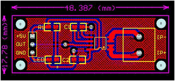
2D Model and Dimensions