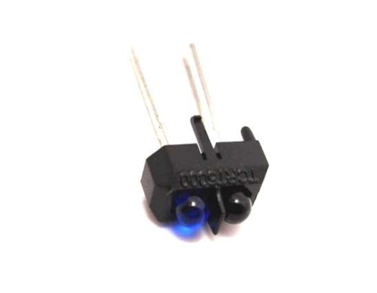
TCRT5000 IR Sensor
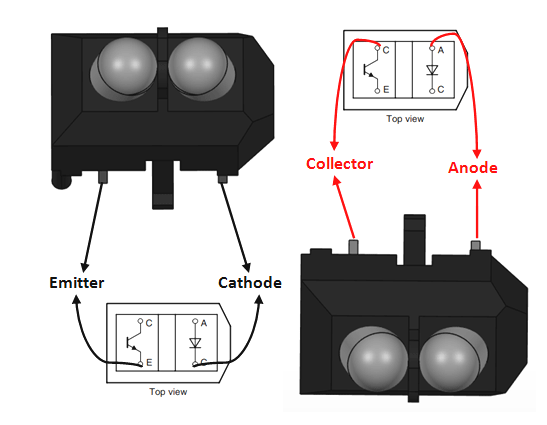
Pin Configuration
|
1 |
Collector |
The collector of the phototransistor is connected to +5V |
|
2 |
Emitter |
The emitter of the phototransistor is grounded through a resistor |
|
3 |
Anode |
The Anode of photodiode is connected to +5V |
|
4 |
Cathode |
The Cathode of photodiode is grounded through a resistor |
TCRT5000 Specifications
- IR sensor with transistor output
- Operating Voltage: 5V
- Diode forward Current: 60mA
- Output: Analog or digital data
- Transistor collector current: 100mA (maximum)
- Operating temperature: -25°C to +85°C
Note: The TCRT5000 datasheet can be found at the bottom of the page
TCRT5000 Equivalent
RPR220
Other IR Sensors
IR Photodiode, IR LED, qtr-1rC, TSOP, GP2Y0A21
Where to use TCRT5000
The TCRT5000 is an IR sensor unit. It has both a Photodiode and a Phototransistor coupled in its package. The photo diode has two pins (Anode and Cathode) which can be used to generate an IR signal. Similarly the Photo transistor also has two pins (Collector and Emitter) which can be used to read the IR signal that is reflected back. This sensor can be used to detect the presence of object or any other reflective surface in front it, also with some level of programming it can also calculate the distance of the object in front it. But the distance can only be calculated for short range objects and is also subjected o environmental disturbance. So if you look for a sensor to measure distance of an object in front of it you should try the HC-SR04 Ultrasonic sensor.
Other than that this sensor is perfect for detecting the proximity of an object in front of it. It can also easily distinguish between black and white colour hence widely used in line following and maze solving robots.
How to use TCRT5000
The TCRT500 sensor is just a combination of a photodiode and a photo transistor. The photo diode is powered through a current limiting resistor of value 220R and the Transistor is also grounded through a 10K resistor as shown in the below picture. The transistor does not have a base pin because the biasing of the transistor is controlled by the amount of IR light it receives. So basically the IR light from the photo diode hits an object/surface and returns back to the photo transistor to bias it.
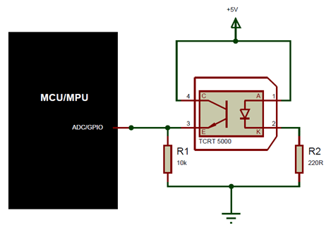
This sensor can either be used as an analog sensor or as a digital sensor. If we only have to detect the presence of an object then the sensor will be used as digital sensor if the distance of the object should also has to be measured then the sensor is used as a analog sensor. For either method the circuit diagram shown above will remain the same.
One major drawback of such IR sensors is that they easily get affected by environmental conditions. Like the photo transistor will not only react to the IR light from the photo diode but will also react to the IR light from Sunlight, house lightings and other commonly available sources. This problem is normally tacked by performing noise cancelation in the program. That is by controlling the photo diode itself through a GPIO pin of the MCU/MPU we can turn off the diode and check how much noise the photo transistor is reading then we can turn on the photo diode and measure the change in values by nullifying the noise that was present while the diode was turned off.
Applications
- Commonly used in proximity detection applications
- Line follower or maze solver robots
- Distinguish between reflective and non-reflective surface
- Obstacle detection and avoidance
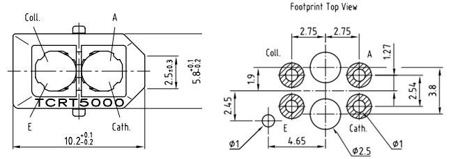
2D-Model