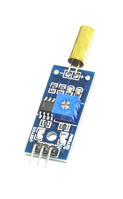
SW-520D - Tilt Sensor Module
TILT SENSOR MODULE is a device used for knowing the planar movement. Although they are available in various types their basic function remains the same. Their function is to detect the plane shift from horizontal to vertical and sent of a signal when it happens. There are modules which could sense even small plane shifts but here we are going to discuss about simple contact type TILT SENSOR module. Here we are going to use SW-520D TILT SENSOR MODULE.
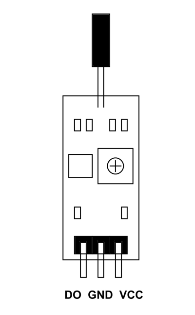
TILT SENSOR MODULE Pin Configuration
TILT SENSOR MODULE is three pin devices as shown in figure. All three pins are compulsory for using the module.
|
Pin Name |
Description |
|
GND |
Connected to GROUND |
|
VCC |
Connected to +5V |
|
DO |
Output of TILT SENSOR |
TILT SENSOR MODULE Features and Specifications
- Supply voltage: 3.3 V to 5V
- Output can directly connected to controller
- TTL level output
- Maximum output current : 15mA
- Can work on low voltages
- Maximum operating temperature: 0°C to + 80°C
- Easy interface
- Long life.
Note: Complete technical information can be found in the SW-520D Tilt Sensor Datasheet linked at the bottom of this page.
Where TILT SENSOR MODULES are Used?
Here are few cases where SW-520D SENSOR MODULE is chosen:
Case1: SW-520D is used when the cost of system cannot be high. SW-520D is one of cheapest and robust TILT SENSORS on the market. It is easily available to replace in case of fault.
Case2: SW-520D is easy to install in the system. All you need to do is power the module appropriately and take the output correctly.
Case3: With very long life this module can be used on permanent installment.
Also the module does not need any additional components to install in a system.
How to Use SW-520D TILT SENSOR MODULE
Before understanding how to use the module let us first understand the working of SW-520D tilt switch. For that consider the internal working of this tilt switch.
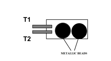
As shown in figure inside SW-520D tilt sensor all we have is two metallic beads. And the output terminals are projected to the inside. When the tilt switch lies horizontally on the plane, the two metallic balls rest on the floor as shown in figure. Under this situation there will no contact between terminals T1 and T2. So T1 and T2 will be open.
Now when the tilt sensor changed position from horizontal to vertical, we have something like this.
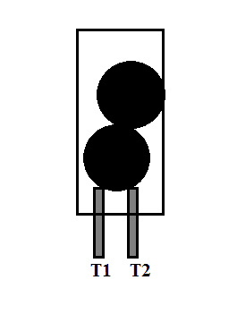
When the tilt switch is moved vertical because of gravity, the metallic balls come to rest on the projected terminals. Because the ball is metallic, when they rest on terminals an electrical contact is formed between two terminals. So in this position T1 and T2 are short circuited.
When the tilt switch is moved to horizontal position again, ball leaves the contact to rest on floor as before. With that T1 and T2 contact breaks making them open circuit.
So SW-520D output terminals open circuit when the body lies horizontal and is short circuit when body is vertical. Hence using this tilt switch we can detect which plane the body is lying.
This tilt switch contact will have noise and cannot be connected to controllers directly. So we will connect this tilt switch to a simple op-amp comparator circuit to make a sensor module.
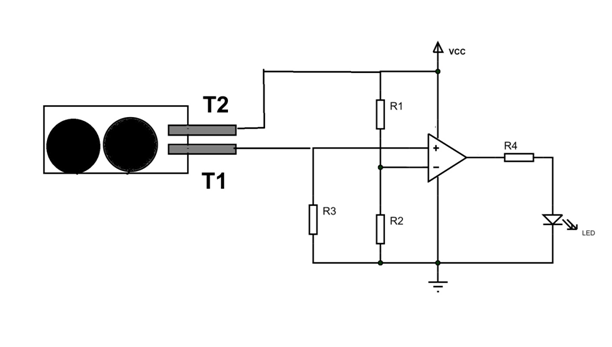
Simplified tilt sensor module is shown in figure. Under normal situations T1 and T2 will be open and the entire VCC appears across it. So voltage at positive terminal of comparator will be zero. So the output of comparator will be low. At this time LED will be OFF.
When the tilt sensor is moved vertical, T1 and T2 will short circuit. At this time entire VCC appears across R3. At this time voltage at positive terminal of comparator will be VCC. With HIGH at positive terminal output of comparator will be HIGH. At this time LED will be ON.
This module output can be given to controller or other systems for using appropriately.
Applications
- Security systems.
- Digital cameras
- Toys
- Motors
- Robotic arms
- Vending machines.
- Measuring instruments.
- Hobby projects.
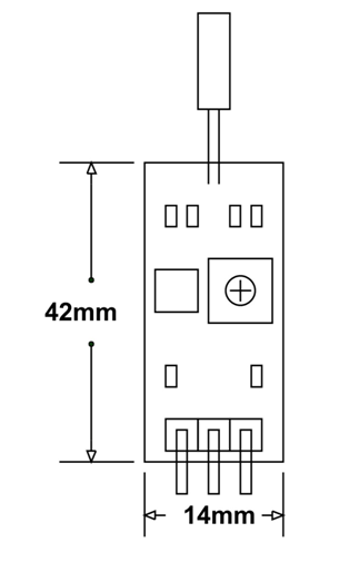
2D Model and Dimensions
All measurements are given in millimeters.
