MS5611 Atmospheric Pressure & Temperature Sensor Module
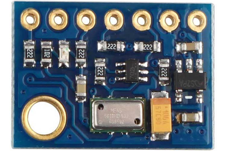
The MS5611 pressure and Temperature sensor module is a hermetically sealed package with a hole to measure ambient pressure. The pressure sensor module consists of the pressure sensor, power supply, and interface circuitry.
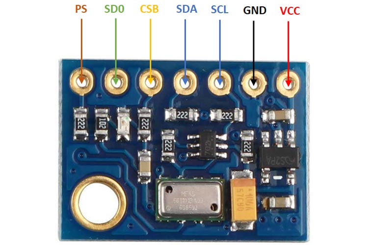
MS5611 Pinout
|
Pin Number |
Pin Name |
Description |
|
1. |
VCC |
Power supply pin, 5V nominal |
|
2. |
GND |
Ground reference |
|
3. |
SCL |
Clock for SPI and I2C |
|
4. |
SDA |
Data for SPI and I2C |
|
5. |
CSB |
Chip select for SPI, Address select for I2C |
|
6. |
SD0 |
Data out for SPI |
|
7. |
PS |
Protocol select, pull high for I2C (default), connect to ground for SPI |
Components Present On MS5611 Module
The following are the major components present in the MS5611 module, which will be described later in the article.
3.3V LDO, MS5611 IC, pullup and pulldown resistors, indicator LED, and decoupling capacitors
Module Specifications
- Supply Voltage – 5V nominal
- Current Draw – approx. 1.5mA
- Pressure range – 10mb to 1200mb
- Altitude resolution – 10cm
- Temperature range - -10°C to 85°C
- SPI and I2C
Note: Complete technical details can be found in the MS5611 Datasheet linked at the bottom of this page.
Alternate Modules
BME280, BMP180, BME680, MPL3115A2
Understanding the MS5611 Module
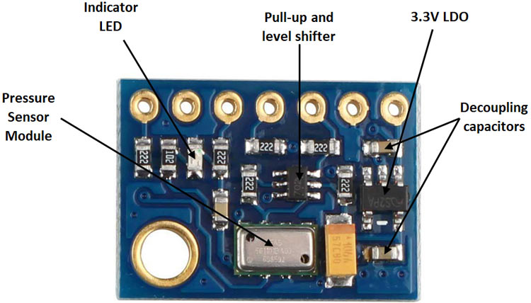
The MS5611 pressure and temperature sensor module consist of the pressure sensor, power supply, and interface circuitry. The pressure sensor module itself is a hermetically sealed package with a hole to measure ambient pressure. Power to the module is provided by a 3.3V low dropout (LDO) regulator and decoupled by two decoupling capacitors. Power is indicated by a single LED.
The module is interfaced to microcontrollers through a level shifter that shifts the 0-3.3V used by the module to the 0-5V used by most microcontrollers. The important connections are broken out to a single row 7 pin header for ease of connection.
Internal Circuit Diagram of MS5611 Module
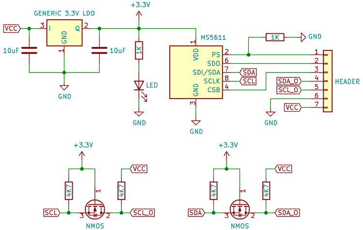
The module is powered by a generic 3.3V LDO. Because of the small package, the LDO cannot handle large currents or voltages and is best powered off with 5V. The LED connected to the 3.3V rail acts as a power indicator.
Since the sensor module itself is not designed to work with 5V signal levels, a discrete level shifter using two N-channel MOSFETs is used. The input is connected to the sources and the output to the drains. When the input is high, the source and gate are both at the same voltage and no current can flow, the drain is therefore high impedance and the output is pulled up through the 4.7K resistor. When the input is low, the gate is at 3.3V with respect to the source and the MOSFET turns on, sinking current through the drain into the pin of the sensor, and the output is low.
The pulldown resistor on the PS pin sets the communication protocol to I2C by default.
How to Use the MS5611 Module
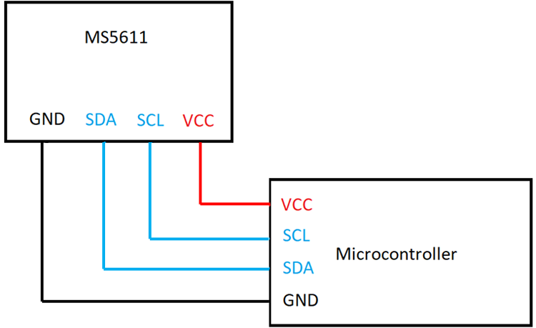
The MS5611 can use both the I2C and SPI protocol, selectable using the PS pin. The pin is pulled low by default, so the I2C protocol is enabled. To talk to the microcontroller, the SCL and SDA pins are connected to the respective SCL and SDA pins on the microcontroller.
There are several libraries for microcontrollers like the Arduino which can be used to gather data from the sensor. In case two sensors are used, the address select pin can be used to change the address of one module using the CSB pin.
Since it is a barometric pressure sensor, it can be used as an altitude measuring device provided it is calibrated to sea-level atmospheric pressure.
MS5611 Module Basic Troubleshooting
If there is no data:
- Check VCC, check of the power indicator LED is glowing
- Check the connection of the data pins
- Check the state of the PS pin and if the right protocol has been programmed to the microcontroller
- Check if the correct clock speed is being used
If the data is incorrect:
- Check if the module has been calibrated correctly
- Check to see if the opening on the sensor is blocked
MS5611 Module Applications
- Weather monitoring
- Altimeter
- Climate control systems
2D Model of the Module
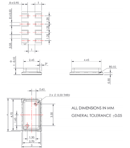
The dimensions of the MS5611 module are given below to help you with selecting the right PCB footprint for MS5611.
