MAX30102 Sensor Oximeter and Heart Rate
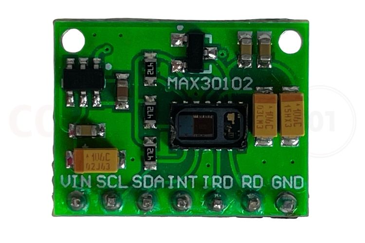
The MAX30102 Sensor is an integrated digital pulse oximeter and Heart Rate Sensor great for its precision and reliability in Health monitoring. With its dual-wavelength LEDs (red and infrared) and high-sensitivity photodetector, the MAX30102 accurately measures blood oxygen saturation (SpO₂) and heart rate (BPM) in real time. Its programmable LED current, 18-bit ADC resolution, and configurable sampling rates enable developers to optimise performance across applications, including wearable fitness devices, medical monitoring systems, and IoT-based health solutions.
Featuring a compact form factor, low power consumption, and an I²C interface, the MAX30102 can be easily used in microcontroller-based projects such as ESP32 and Arduino platforms. With stable long-term performance, it provides reliable and continuous physiological data, making it an essential component for health monitoring, research, and automated wellness systems.
MAX30102 Sensor Quick Specifications
| Parameter | Specification |
|---|---|
| Sensor Type | Integrated Pulse Oximeter & Heart Rate Monitor |
| Communication Interface | I²C (Address: 0x57) |
| Operating Voltage | 1.8V (Core), 3.3V (LEDs), Module: 3.3V-5V |
| Current Consumption | 600μA (Active), 0.7μA (Standby) |
| ADC Resolution | 18-bit |
| LED Wavelengths | Red: 660nm, Infrared: 880nm |
| Sample Rate Range | 50-3200 samples per second (configurable) |
| FIFO Buffer Depth | 32 samples |
| Package Type | 14-pin OESIP (Optical Enhanced System-In-Package) |
| Temperature Sensor | Built-in (±1°C accuracy, -40°C to +85°C) |
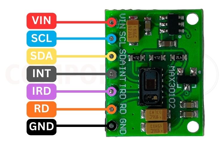
MAX30102 Pinout Configuration
Understanding the MAX30102 pinout is essential for proper sensor integration. The MAX30102 pin diagram clearly outlines essential connections such as VIN for power, SDA/SCL for I²C communication, and dedicated IRD/RD pins for LED control.
|
Pin |
Function |
Description |
|
VIN |
Power supply |
5V Supply input |
|
SCL |
I²C Clock |
Serial clock line for communication |
|
SDA |
I²C Data |
Serial data line for communication |
|
INT |
Interrupt |
Signals when new data is ready |
|
IRD |
Infrared LED Control |
Controls the infrared LED |
|
RD |
Red LED Control |
Controls the red LED |
|
GND |
Ground |
Connect to system ground |
Key Features and Technical Specifications of MAX30102 Sensor
The MAX30102 sensor incorporates advanced features that make it suitable for professional health monitoring applications. The MAX30102 datasheet from Analog Devices highlights several advanced features that distinguish this sensor from alternatives like the MAX30100:
-
High-Precision 18 Bit ADC promotes maximum signal resolution and minimum noise level in SpO2 and heart rate measurement.
-
Dual LED Configuration provides independent control of Red (660nm) and Infrared (940nm) LED's which includes programmable current (0 to 50 mA).
-
I2C Communication has a standard two-wire interface with a 7-bit address 0x57 to facilitate microcontroller integration.
-
Ultra Low Power Consumption 600 µA when measuring in active mode, but only 0.7 µA when in power-save mode; both are perfect for battery-operated/portable devices.
-
A 32 Level FIFO buffer allows the internal memory to hold multiple data, thus decreasing the frequency of interrupts needed by the microcontroller.
-
Programmable Sample Rates from 50 to 3200 samples/second allow you to provide multiple options to fit your application requirements.
-
Ambient Light Cancellation (ALC) & circuits allow up to 200µA of interference from ambient light to be eliminated.
-
Built-In Temperature Sensor measures the die temperature with a temperature range of -40°C to +85°C, and is accurate to ±1°C to assist with calibration.
-
Flexible LED Pulse Width range is from 69 µs to 411 µs, thus allowing you to optimise both current consumption and measurement accuracy.
-
Operating Voltage range supports operation using onboard regulators that provide 1.8 V to the sensor IC and 3.3V to 5V to the module.
MAX30102 Sensor Alternatives and Comparison
When selecting a pulse oximeter sensor, it's important to understand the available MAX30102 sensor alternatives and their comparative advantages of MAX30102, MAX30101, MAX30105, MAXREFDES103 / MAXREFDES117
| Feature | MAX30102 | MAX30100 | MAX30101 | MAX30105 |
|---|---|---|---|---|
| LEDs | Red + IR (2 LEDs) | Red + IR (2 LEDs) | Red + IR (2 LEDs) | Red + IR + Green (3 LEDs) |
| ADC Resolution | 18-bit | 16-bit | 18-bit | 18-bit |
| FIFO Depth | 32 samples | 16 samples | 32 samples | 32 samples |
| Max Sample Rate | 3200 sps | 1000 sps | 3200 sps | 3200 sps |
| Power Consumption | 600μA (typical) | 1000μA (typical) | 600μA (typical) | 600μA (typical) |
| Temperature Sensor | Yes (integrated) | Yes (integrated) | Yes (integrated) | Yes (integrated) |
| Primary Application | SpO₂ + Heart Rate | SpO₂ + Heart Rate | SpO₂ + Heart Rate | Multi-LED Bio-sensing |
| Best For | Wearables, Low Power | Budget Projects | High Performance | Research, Particle Detection |
Note: Complete technical details and application circuits can be found in the MAX30102 datasheet. The breakout module discussed in this article is commonly available from SparkFun or similar vendors
MAX30102 Module Schematic and Circuit Design
The MAX30102 module schematic reveals the sensor's internal architecture and external component requirements. The MAX30102 datasheet specifies that the sensor chip requires 1.8V for internal operation, while the LEDs operate at 3.3V.
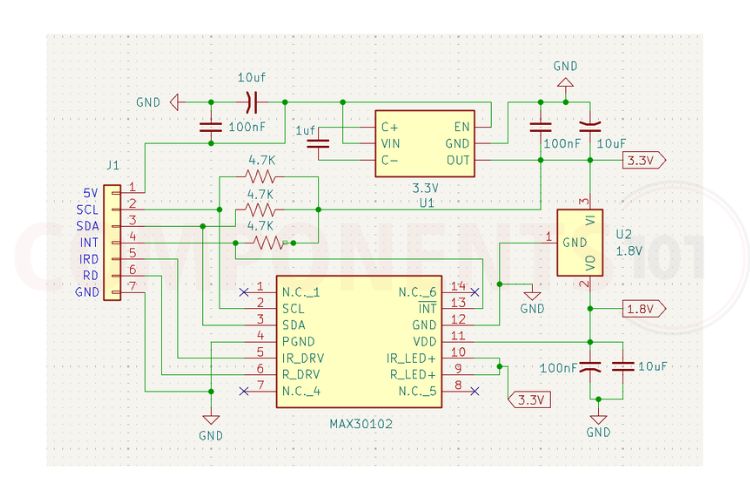
Key Components in MAX30102 Module
✓ Voltage Regulator (AP2112K) - Provides a stable 3.3V output when powered from a 3.3V-5.0V input for the LED's power supply (VLED).
✓ LDO Voltage Regulator (TLV70018) - Produces a regulated 1.8V supply voltage necessary for the MAX30102's VCore.
✓ Decoupling Capacitors - 4.7uF & 0.1uF are used on both rails of VLED & VCORE to reduce power rail noise and to improve stability of circuits powered by those rails.
✓ I²C Pull-Up Resistors - 4.7K ohms pull up both SDA & SCL (21,22) to VDD. Very important to have a resistor between VDD and these two signals. Refer to the hardware issues below regarding this topic.
✓ LED Filter Capacitors - For reducing the amount of power delivered to the LEDs.
Important: MAX30102 Hardware Issue
Some MAX30102 breakout boards have a hardware design issue where the onboard 4.7 kΩ I²C pull-up resistors are connected to the module’s 1.8 V supply. Since most microcontrollers use a 3.3V I²C bus, this low pull-up voltage prevents the sensor from appearing in I²C scans and stops proper LED operation. To resolve this, the 1.8V trace supplying the pull-ups must be disconnected, and the resistors should be rewired to the 3.3V supply instead. After rerouting the pull-ups to 3.3V, the MAX30102 becomes detectable on the I²C bus and functions correctly.
Interfacing MAX30102 with Arduino
Connecting the MAX30102 sensor with Arduino is straightforward using the I²C communication protocol. Shown below is the wiring configuration used to interface the MAX30102 sensor with Arduino.
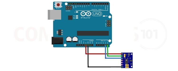
The MAX30102 sensor communicates with Arduino using the I2C protocol. The SDA pin of the sensor connects to Arduino’s A4, while the SCL pin connects to A5. Power is supplied through the VIN and GND pins.
Arduino to MAX30102 Wiring Connections:
| MAX30102 Pin | Arduino Uno Pin | Connection Notes |
|---|---|---|
| VIN | 5V (or 3.3V) | Power supply input; module accepts 3.3V-5V |
| GND | GND | Common ground connection |
| SCL | A5 (SCL) | I²C clock line (on Mega: Pin 21) |
| SDA | A4 (SDA) | I²C data line (on Mega: Pin 20) |
| INT | Optional (any digital pin) | Interrupt pin for event-driven operation (not required for basic use) |
Programming MAX30102 with Arduino IDE: Library Installation and Code
To program the MAX30102 sensor, you need to install the appropriate MAX30102 library in the Arduino IDE.
Installing the MAX30102 Library:
- Open Arduino IDE
- Navigate to Sketch → Include Library → Manage Libraries
- Search for "MAX30105" or "SparkFun MAX3010x"
- Install SparkFun MAX3010x Pulse and Proximity Sensor Library by SparkFun Electronics
- The library supports MAX30102, MAX30105, and MAX30101 sensors
Here is the sample code for the interface. Make sure to download and install the required MAX30102 library in Arduino IDE.
#include <Wire.h>
#include "MAX30105.h"
#include "spo2_algorithm.h"

MAX30105 particleSensor;

#define BUFFER_SIZE 50  // smaller buffer for faster testing

uint16_t irBuffer[BUFFER_SIZE];
uint16_t redBuffer[BUFFER_SIZE]

int32_t spo2;
int8_t spo2Valid;
int32_t heartRate;
int8_t hrValid;

void setup() {
  Serial.begin(115200);
  Wire.begin();

  if (!particleSensor.begin(Wire, I2C_SPEED_FAST)) {
    Serial.println("MAX30102 not found. Check wiring!");
    while (1);
  }

  Serial.println("Place your finger gently on the sensor...");

  particleSensor.setup();
  // Optimized LED brightness to avoid saturation
  particleSensor.setPulseAmplitudeRed(0x1F);
  particleSensor.setPulseAmplitudeIR(0x1F);
}

void loop() {
  // Collect samples
  for (int i = 0; i < BUFFER_SIZE; i++) {
    while (!particleSensor.available())
      particleSensor.check();

    redBuffer[i] = particleSensor.getRed();
    irBuffer[i] = particleSensor.getIR();

    particleSensor.nextSample();
  }

  // Print raw IR/RED values for debugging
  Serial.print("IR=");
  Serial.print(irBuffer[BUFFER_SIZE/2]);
  Serial.print("  RED=");
  Serial.println(redBuffer[BUFFER_SIZE/2]);

  // Run heart rate & SpO2 algorithm
  maxim_heart_rate_and_oxygen_saturation(
    irBuffer, BUFFER_SIZE,
    redBuffer, &spo2, &spo2Valid,
    &heartRate, &hrValid
  );

  // Print results
  Serial.print("SpO2: ");
  if (spo2Valid) Serial.print(spo2);
  else Serial.print("Invalid");

  Serial.print("  BPM: ");
  if (hrValid) Serial.print(heartRate);
  else Serial.print("Invalid");

  Serial.println();

  delay(1000); // Update every second
}
Real-World Applications of MAX30102 Sensor
The versatility and accuracy of the MAX30102 pulse oximeter sensor make it suitable for numerous health monitoring and biomedical applications:
- Wearable Fitness Trackers: Heart rate data will continue to be collected while exercising, and SpO₂ (oxygen saturation in blood) will be monitored via a Bluetooth-enabled, connected device
- Smart Companion Watches/Fitness Bands: Health monitoring is available 24/7 due to the low battery consumption of sleep tracking devices
- Medical-Rated Pulse Oximeters: These units are designed to be used in commercial settings and for consumer-based home therapy; they are not presently an FDA-approved product.
- Health Monitoring Systems Using IoT Technology: The use of ESP32/ESP8266 technology paired with a cloud-connected Health Dashboard allows patients to experience a complete remote monitoring experience.
- Detecting Sleep Apnea Patterns: Monitoring overnight SpO₂ to identify poor breathing patterns as well as incidents when the oxygen level drops in the blood
- Preventing High-Altitude Sickness: It will allow a person to track the amount of oxygen they have in their blood while engaging in activities at high altitudes and within mountain climbing expeditions.
- COVID-19 Devices: Early identification of blood oxygen levels will indicate the presence of a potential respiratory illness.
Research and Development of Biomedical Engineering Projects/University Developed Projects/Clinical Trials. - Monitoring and caring for Elderly Individuals: Remote monitoring systems are provided for senior living facilities and in-home elderly care.
MAX30102 Sensor Module Dimensions and Physical Specifications
Understanding the MAX30102 dimensions is crucial for PCB layout design and enclosure planning.
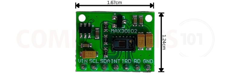
The MAX30102 sensor represents a powerful, cost-effective solution for integrating pulse oximetry and heart rate monitoring into embedded systems and wearable devices.


