MIC5219: 500 mA Peak Output LDO Regulator
The MIC5219 is an efficient linear voltage regulator with high peak output current capability of 500mA, very low dropout voltage (500mV at full load), and better than 1% output voltage accuracy. Approx. zero power consumption in a disabled condition makes it suitable for battery-powered equipment and linear voltage supplies.
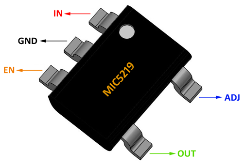
Pin Configuration
|
Pin No. |
Pin Name (Fixed Ver.) |
Pin Name (Adj. Ver.) |
Description |
|
1 |
IN |
IN |
Supply Input |
|
2 |
GND |
GND |
Ground |
|
3 |
EN |
EN |
Enable/Shutdown (Input): CMOS compatible input. Logic-high = enable, logic-low or open = shutdown |
|
4 |
BYP |
ADJ |
Reference Bypass: Connect external 470 pF capacitor to GND to reduce output noise. May be left open. Adjust (Input): Adjustable regulator feedback input. Connect to resistor voltage divider |
|
5 |
OUT |
OUT |
Regulator Output |
Features
- Input Supply Voltage: 2.5V to 12V
- Output Voltage Min.: 3.3 V
- Peak Output Current: 500mA
- Drop-out Voltage: 500mV at 500mA
- Enable Logic HIGH: 3 V
- Enable Logic LOW: 0.4 V
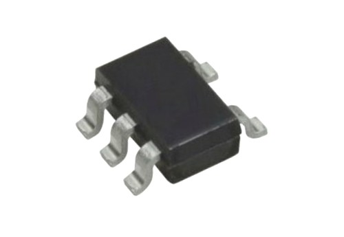
- Available in SOT-23-5 & MSOP-8 Package
Note: The Complete Technical Details can be found at the datasheet given at the end of this page.
Equivalent for MIC5219: SPX3819, MAX3890, LP2989
Alternative LDO Regulators: LP2985, AMS1117, MIC5225
MIC5219 Introduction
The MIC5219 is a Low Drop Out voltage regulator from Microchip. It is capable of regulating voltage efficiently without dropping much voltage across the regulator and can provide output voltage almost close to the input voltage. The regulator has a maximum output current of 500mA during which it drop-out voltage across the regulator is only 500mV. The input voltage of the Regulator can be between 2.5V to 12V. The output voltage of the MIC5205 can be from 2.5V to 5V, you can use the below table to select the right part number. Also do remember that the input voltage should be higher by 1 than output voltage (VIN = VOUT + 1).
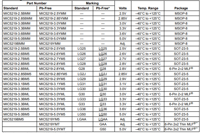
When shut down, power consumption by this regulator drops nearly to zero and due to this feature MIC5219 is commonly used in high current battery operated applications.
How to use the MIC5219
Below circuit shows the basic circuit for the MIC5219 adjustable regulator. The output voltage can be adjusted to specific value by selecting values for R1 and R2 using the following formula
V = 1.242V × (R2\R1 + 1)
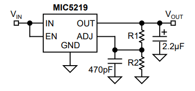
470pF bypass capacitor from ADJ to GND is used to reduce the output noise. The Adjust pin is used to set the output voltage of the regulator to the required value while enable pin can be used turn on or off the regulator, this helps to turn off the regulator and prevent battery usage when not in use.
Applications
- Cellular Telephones
- Laptop, Notebook, and Palmtop Computers
- Battery-Powered Equipment
- PCMCIA VCC and VPP Regulation/Switching
- Consumer/Personal Electronics
- SMPS Post-Regulator and DC/DC Modules
- High-Efficiency Linear Power Supplies
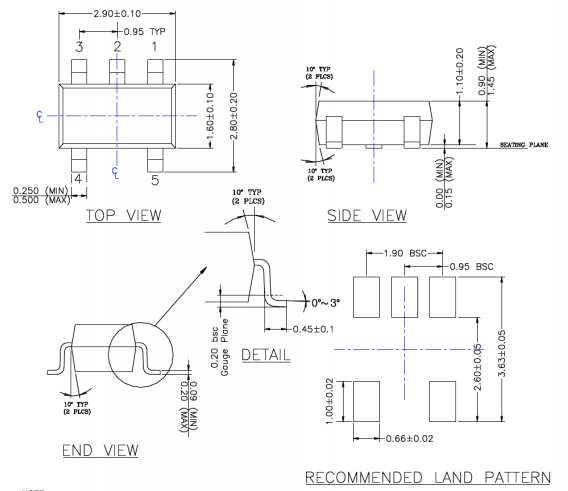
2D-Model