LM4041 Improved Precision Micropower Shunt Voltage Reference

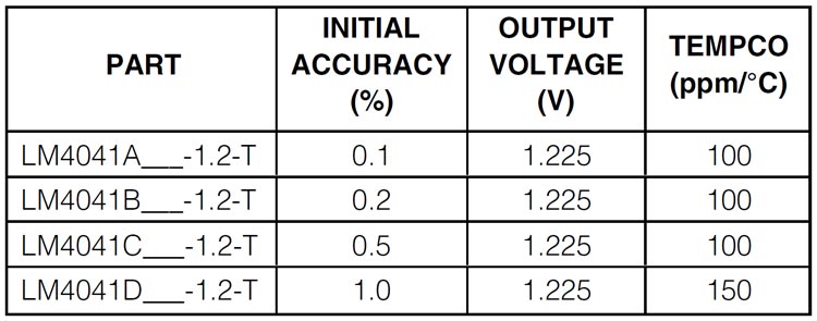
The LM4041 is a highly precise, two-terminal shunt mode, bandgap voltage reference that is perfect for applications where space is at a premium. Its reverse breakdown voltage is fixed at 1.225V. To ensure optimal accuracy, the LM4041 features laser-trimmed resistors that provide precise initial accuracy. With a temperature coefficient of 100ppm/°C, this device is available in four grades of initial accuracy, ranging from 0.1% to 1%. Additionally, the LM4041 has a shunt current capability of 60µA to 12mA, along with a low dynamic impedance that helps to ensure stable reverse-breakdown voltage accuracy over a wide range of operating temperatures and currents. The LM4041 is available in a 3 pin SC70 package. All in all, the LM4041 is an impressive device that is sure to meet the needs of those in need of precise voltage references in tight spaces.
LM4041 Pinout Configuration
|
Pin Number |
Pin Name |
Description |
|
1 |
+ |
Positive Terminal |
|
2 |
- |
Negative Terminal |
|
3 |
NC |
Leave unconnected, or connect to pin 2 |
Features
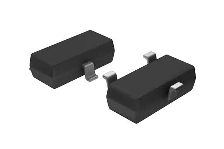
- Ultra-Small 3-Pin SC70 Package
- 0.1% (max) Initial Accuracy
- 100ppm/°C (max) Temperature Coefficient Guaranteed over -40°C to +125°C Temperature Range
- Wide Operating Current Range: 60µA to 12mA
- Low 20µVRMS Output Noise (10Hz to 10kHz)
- 1.225V Fixed Reverse Breakdown Voltage
- No Output Capacitors Required
- Tolerates Capacitive Loads
LM4041 Alternative
Zener Diodes, TL431 (Programmable),
Variants
How To Use LM4041 Voltage Reference?
The LM4041 shunt references use the bandgap principle to produce a stable, accurate voltage. The device behaves similarly to an ideal Zener diode; a fixed voltage of +1.225V is maintained across its output terminals when biased with 60μA to 12mA of reverse current. It will also behave like a silicon diode when it is forward biased with a current of 10mA. The image below shows the typical application diagram of the LM4041.
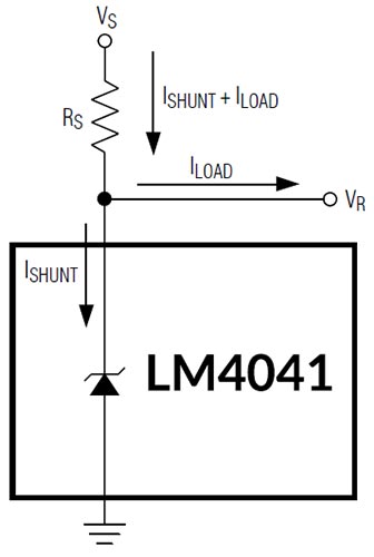
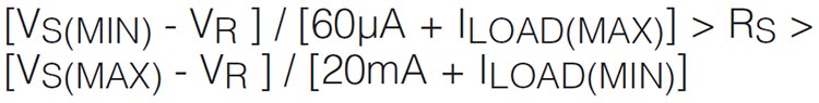
Choose the value of Source resistor(Rs) with minimum vs and maximum load current in mind. Maintain a minimum Ishunt of 60uA at all times. The RS value should be large enough to keep ISHUNT less than 12mA for proper regulation when VS is maximum and ILOAD is at a minimum. To prevent damage to the device, ISHUNT should never exceed 20mA. Use the following equation to calculate the value of resource resistance:
Applications
- Cell Phones
- Industrial Process Controls
- Notebook Computers
- Portable Battery-Powered Equipment
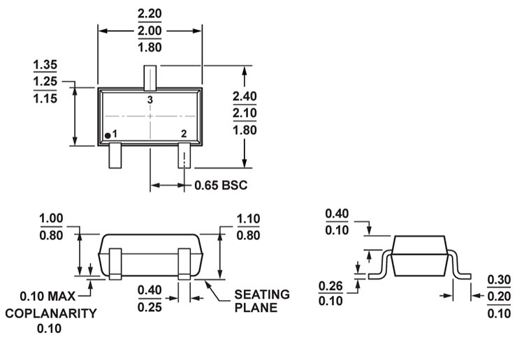
2D-Model and Dimensions