LM317 Variable Voltage Regulator
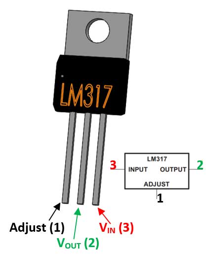
LM317 Pin Configuration
|
Pin Number |
Pin Name |
Description |
|
1 |
Adjust |
This pins adjusts the output voltage |
|
2 |
Output Voltage (Vout) |
The regulated output voltage set by the adjust pin can be obtained from this pin |
|
3 |
Input Voltage (Vin) |
The input voltage which has to be regulated is given to this pin |
Features
- Adjustable 3-terminal positive voltage regulator
- Output voltage can be set to range from 1.25V to 37V
- Output current is 1.5A
- Maximum Input to output voltage difference is 40V, recommended 15V
- Maximum output current when voltage difference is 15V is 2.2A
- Operating junction temperature is 125°C
- Available in To-220, SOT223, TO263 Package
Note: Complete Technical Details can be found at the LM317 datasheet given at the end of this page.
Alternative Voltage Regulators
LM7805, LM7806, LM7809, LM7812, LM7905, LM7912, LM117V33, XC6206P332MR.
LM317 Equivalents
LT1086, LM1117 (SMD), PB137, LM337 (Negative Variable Voltage regulator)
Where to use LM317
When it comes to variable voltage regulation requirements LM317 would most likely be the first choice. Apart from using it as a variable voltage regulator, it can also be used as a fixed voltage regulator, current limiter, Battery charger, AC voltage regulator and even as an adjustable current regulator. One notable drawback of this IC is that it has a voltage drop of about 2.5 across it during regulation, so if you looking to avoid that problem look into the other equivalent IC’s given above.
So, if you are looking for a variable voltage regulator to deliver current up to 1.5A then this regulator IC might be the right choice for your application.
How to use LM317
LM317 is a 3-terminal regulator IC and it is very simple to use. It has many application circuits in its datasheet, but this IC is known for being used as a variable voltage regulator. So, let’s look into how to use this IC as a variable voltage regulator.
As said earlier the IC has 3 pins, in which the input voltage is supplied to pin3 (VIN) then using a pair of resistors (potential divider) we set a voltage at pin 1 (Adjust) which will decide the output voltage of the IC that is given out at pin 2 (VOUT). Now to make it act as a variable voltage regulator we have to set variable voltages at pin 1 which can be done by using a potentiometer in the potential divider. The below circuit is designed to take 12V (you can supply up to 24V) as input and regulate it from 1.25V to 10V.
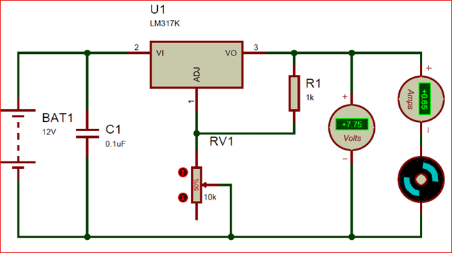
The Resistor R1 (1K) and the potentiometer (10k) together creates a potential difference at adjust pin which regulates the output pin accordingly. The formulae to calculate the Output voltage based on the value of resistors is-
VOUT = 1.25 × (1 + (R2/R1))
Now, let’s verify this formula for the above circuit. The value of R1 is 1000 ohms and the value of R2 (potentiometer) is 5000 because it is a 10k potentiometer placed at 50% (50/100 of 1000 is 5000).
Vout = 1.25 × (1 + (5000/1000))
= 1.25 × 6
= 7.5V
And the simulation shows 7.7 V which is pretty much close. You can vary the output voltage by simply varying the potentiometer. In our circuit, a motor is connected as a load which consumes around 650mA you can connect any load up to 1.5A.
The same formulae can also be used to calculate the value of resistor for you required output voltage. One easy way to do this is to use this online calculator to randomly substitute the value of resistors you have and check which output voltage you will get.
Applications
- Used for Positive voltage regulations
- Variable power supply
- Current limiting circuits
- Reverse polarity circuits
- Commonly used in Desktop PC, DVD and other consumer products
- Used in motor control circuits
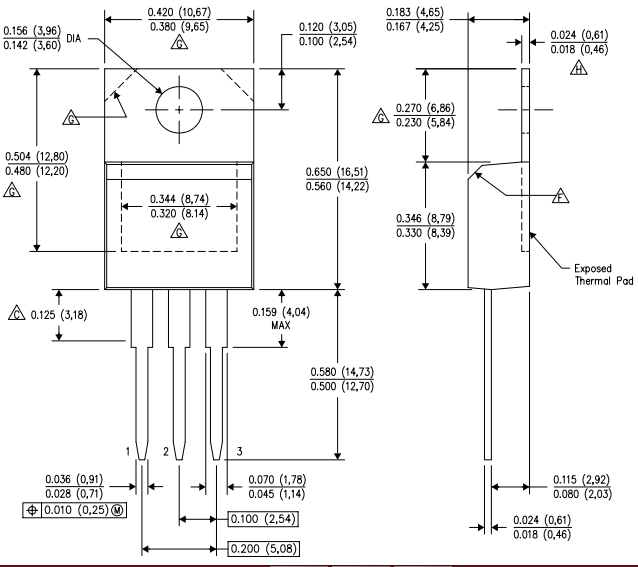
2D – Model of LM317 (TO-220)