LD1117 Fixed/Variable Voltage Regulator
LD1117 is a Positive Voltage Regulator with a very low Voltage drop across it. Based on the version of the IC the output voltage can vary between fixed voltages like 1.2V, 1.8V, 2.5V, 2.85V, 3.0V, 3.3V, 5.0V or can also be a variable voltage regulator.
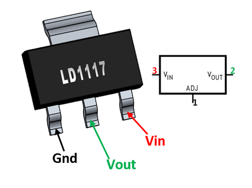
Pin Configuration
|
Pin Number |
Pin Name |
Description |
|
1 |
Ground |
Ground Pin – connected to ground of the system. |
|
2 |
Vout |
Regulated Output Voltage |
|
3 |
Vin |
Input Voltage that is to be regulated |
Features
- Positive Voltage Regulator with Low voltage drop
- Output Voltage can be Fixed/Variable based in version.
- Output Voltage: 1.2V, 1.8V, 2.5V, 2.85V, 3.0V, 3.3V, 5.0V or variable
- Output Current: 800mA
- Maximum Input Voltage: 15V
- Available in TO-220, SOT-223, SO-8 and DPAK
Note: Complete Technical Details can be found at the LD1117 datasheet given at the end of this page.
LD1117 Alternatives
KIA78xxP, LM1117
Other Voltage Regulators
Where to use LD1117 Regulator
Just like the popular LM317, the LD1117 is also another Linear Voltage regulator. It is known for its small form factor since it is available as a DCY Package (SMD Component). There are many types of LD1117, the fixed types provide a fixed output voltage of 1.8V, 2.5V, 3.3V or 5V and also a variable voltage Regulator with a reference voltage of 1.25V. It is very similar to the LM1117 but the LD1117 ha very low voltage drop making it suitable for battery operated applications.
So if you are looking for a SMD component voltage regulator with low voltage drop then this IC might be the right choice for you.
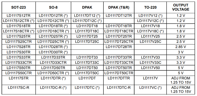
Selecting the right LD1117
The LD1117 Output voltage will differ based on its part number. Also the IC is available in four different packages. The following table will be useful to select the suitable IC with correct voltage rating and package type.
How to use LD1117
Using the LD1117 is pretty much straight forward. If it a fixed voltage regulator just power the IC though the Vin pin and the regulated output can be obtained in the Vout pin. The Adj/Ground pin in this case acts only as a ground pin and is grounded. Also a capacitor can be added at the output side to filter out the noise.
For an Adjustable type voltage regulator we need two external resistors to decide the output voltage of the Regulator. A reference circuit diagram is shown below, where the resistors R1 and R2 decides the output voltage of the regulator. The capacitor CAdj is an optional component which can be added to improve ripple rejection if required. The other two capacitors are to filter the input and output noise respectively. The application circuit and other important parameters can be referred from the datasheet linked below.
Applications
- Used for Positive voltage regulations
- Battery Operated applications.
- Variable power supply
- Current limiting circuits
- Reverse polarity circuits
- Commonly used in Desktop PC, DVD and other consumer products
- Used in motor control circuits
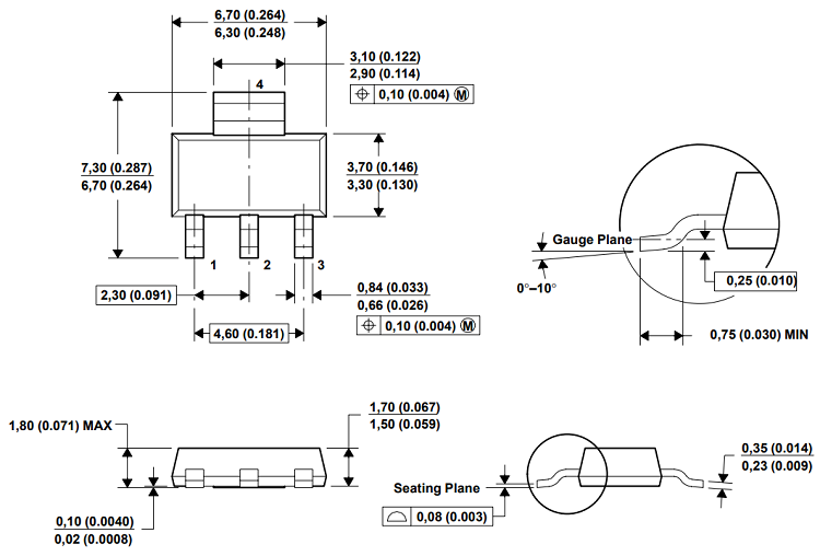
2D – Model of LD1117