AD620 Instrumentation Amplifier

The AD620 is a low cost, high accuracy instrumentation amplifier that requires only one external resistor to set gains of 1 to 10,000. The AD620 features 8-lead SOIC and DIP packaging that is smaller than discrete designs and offers lower power (only 1.3 mA max supply current), making it a good fit for battery-powered, portable (or remote) applications.
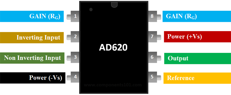
Pin Description of AD620:
|
Pin Number |
Pin Name |
Description |
|
1 |
Gain (Rg) |
Inverting Gain Terminal connected to a resistor to set gain value |
|
2 |
Inverting Input (IN-) |
The Inverting input pin of the Op-Amp |
|
3 |
Non- Inverting Input (IN-) |
The Non - Inverting Input Pin of Amplifier |
|
4 |
Power (-Vs) |
Negative supply terminal |
|
5 |
Reference |
Output reference input. Normally connected to common |
|
6 |
Output |
Amplifier output pin |
|
7 |
Power (+Vs) |
Positive supply terminal |
|
8 |
Gain (Rg) |
Non - Inverting Gain Terminal connected to resistor to set gain value |
AD620 Features & Specifications:
- Power Supply Range: ±2.3 V to ±18 V
- Max Supply Current: 1.3 mA
- Input Offset Voltage: 50 μV
- Bandwidth:120 kHz
- Input Offset Drift: 0.6 μV/°C
- Input Bias Current: 1.0 nA max
- Available in 8-Pin PDIP,SOIC packages
Note: Complete Technical Details can be found at the AD620 datasheet give at the end of this page.
Equivalent for AD620: AD623
Alternatives Amplifiers: LM4871, IC6283, JRC45558
Where to use the AD620 Instrumentation Amplifier?
The AD620, with its high accuracy of 40 ppm maximum nonlinearity, low offset voltage of 50 μV max, and offset drift of 0.6 μV/°C max, is ideal for use in precision data acquisition systems, such as weigh scales and transducer interfaces. Furthermore, the low noise, low input bias current, and low power of the AD620 make it well suited for medical applications, such as ECG and non-invasive blood pressure monitors.
How to use AD620:
The AD620 only requires a resistor to sets its gain value and hence can be easily set up. A very basic commonly used circuit for AD620 is shown below.
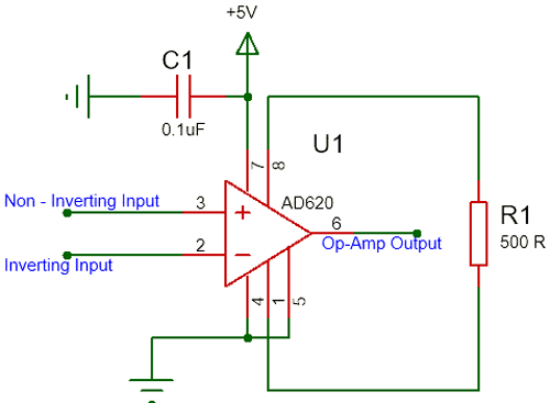
The IC is powered using the pin 7 and pin 4 is connected to ground. Here I have used a singly supply of +5V. The non - inverting pin (pin 2) and the inverting pin (pin 3) is connected the signal which has to be amplified or compared base on the application of the Op-Amp. The Reference pin (pin 5) is normally grounded along with pin 4, the reference pin is used to direct the output towards a voltage when the difference voltage between the inverting and the non-inverting pin is 0V.
The Gain of an Op-Amp can be set by simply connecting the right value of resistor across the pin +Rg (pin 8) and the pin –Rg (pin 1). Here I have connected a resistor of value 500Ω which will set the Op-Amp at a gain value of 100. The formulae to calculate the value of gain from R is given below
G = (49.4 kΏ / RG) + 1
Applications of AD620:
- Weigh scales
- ECG and medical instrumentation
- Transducer interface
- Data acquisition systems
- Industrial process controls
- Battery-powered and portable equipment
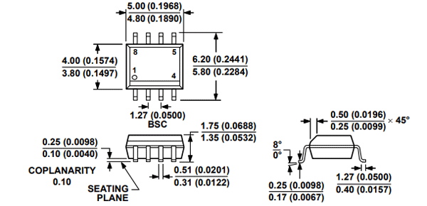
2D-Model AD620:
2-D dimensions for AD620 8-pin SOIC package is given below