

Optimized with highly sensitive cap touch sensors, extensive peripheral circuits and 125℃ operation
Introduction to RFID Modules – Construction, Types and Working
The term RFID stands for Radio Frequency Identification, as the name defines the operation of the device is based on the Radio frequency signals. The RFID systems consists of RFID Reader and a tag which is normally used in identification and tracking of objects. Before discussing more about the RFID, let’s see the uniqueness of this technology and its general application. Today in most cases barcodes are used for identifying an item in a warehouse or a supermarket using a barcode scanner, this existing system can be upgraded with the RFID technology. Similar to barcode the RFID can also give unique identification number to all products but the added advantage is unlike the barcode system’s line of sight, this system can detect the RFID tag within its proximity range. Meaning you do not need a human to search for the barcode and point the barcode scanner on it. With this feature most of the system can be automated and human intervention can be minimized because the tag can be scanned and billed automatically when it reaches the RFID reader. RFID door locks and RFID attendance system are very popular now days and many hotels provide provide RFID tag to their customer to lock and unlock the door.
RFID System Construction
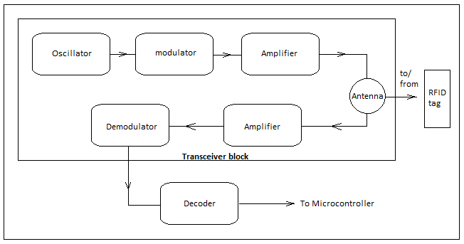
Any RFID System will consist of a RFID reader and a RFID tag. The tag will often be small and portable with little to no electronics in it. We will learn more about the tags later in this article, a simple RFID system can be represented using the below block diagram.
Now let us discuss about each components in the block diagram construction briefly.
RFID Reader
It is a device which consists of an antenna, transceiver and a decoder.
- Transceiver: It can be used either as a transmitter or a receiver. It consists of an oscillator to generate a continuous signal which is modulated to a required frequency and then transmitted into air through an antenna.
- Antenna: It is a device which converts the electrical signal into electromagnetic signal which is efficient in propagating the signal in air.
- Decoder: When a RF signal is detected at the antenna from a tag, the decoder helps in retrieving the data.
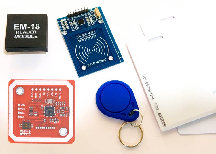
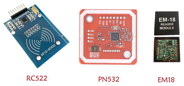
Below are the images of three popular RFID Readers – EM18 RFID Reader Module, RC522 RFID Module and PN532 NFC RFID Module.
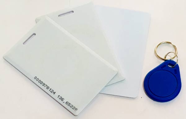
RFID Tag
It consists of 2 components (in case of a passive tag). They are Microchip and an antenna. You can know more about RIFD Tags here.
- Microchip: It is a semiconductor device which consists of a circuit etched in it with some KB of memory storage, capable of storing data and transmitting it whenever needed.
- Antenna: It is used to transmit the data that is present in the chip into air so that it can be detected by a reader.
Incase of an active tag it consists of Microchip, battery and an antenna
- Battery: In active devices in order to power up the microchip battery is externally used.
How does RFID work? Working principle of RFID system
A RFID reader stays powered on all the time and is normally powered from an external power source. So when it is ON, the oscillator in it generates a signal with a desired frequency but as the signal strength will be very less (which may lead to fading off the signal if it is transmitted directly) it has to be amplified which can be done using an amplifier circuit, inorder to propogate the signal to a longer distance we need to modulate the signal which is done by a modulator. With all these improvements the signal is now ready to be transmitted which can be done by an antenna which converts the electrical signal into a electromagnetic signal.
The RFID reader signals are everywhere with it’s promity to detect a tag. When a RFID tag comes in the proxmity of the RFID reader the tag detects the readers signal through a coil present in it which converts the received RF signal into a electrical signal. This converted signal alone is sufficient to power up the microchip present in the tag. Once the microchip gets powered up, its function is to send the data (unique ID) which it is stored in it. The same way the signal came in, it is sent out through the same coil into the air.
As discussed earlier the RFID reader also has a transceiver in it. When the signal comes back from the tag through the antenna of RFID reader it is fed to the demodulator and then decoded by a decoder where the original data can be obtained and then further processed by a microcontroller or a microprocessor to perform a specific task.
Note that the above explanation is for a passive RFID tag. In case of an active RFID tag it detects the signal from the reader only to trigger the circuit and make the tag ready to send the data to the reader, since active tags have built-in power source.
Frequency Range used by RFID Technology
We know that the Radio frequency range is from 3 kHz to 300 GHz but the RFID generally uses Radio frequencies in ranges within the Radio frequency (RF) band categorized as below:
- Low frequency RFID: Its range is in between 30 kHz to 500 kHz but the exact frequency used by it is 125 kHz. Its detection range is 10 -15 cm.
- High frequency RFID: Its range is in between 3 MHz to 30 MHz, the exact frequency used by the module is 13.56 MHz. Its detection range is up to 1.5 meters.
- Ultra High frequency RFID: Its range is 300 MHz to 960 MHz but the exact frequency used is 433 MHz. The detection range is up to 20 meters.
- Microwave RFID: It uses a frequency of 2.45 GHz and the detection range is up to 100 meters far.
So based on the application and the detection range required the suitable RFID should be chosen. The detection range varies based on the size of antenna size and tuning.
Types of RFID systems
The RFIDs are broadly categorized into two types mainly based on the type of RFID tag used. The two systems are called Active RFID system and Passive RFID system.
1. Active RFID system
The Active RFID system has active tags which are powered up with a power source (a battery). So the active tags are capable of radiating their own Radio frequency signals to transmit the data that contains in the microchip, without depending upon the Reader’s signals to power up.
The active RFIDs are typically categorized under UHF RFID which has detection range up to 20 meters. These active tags are further categorized into Transponders and Beacons
- Transponders:
As the name itself specifies that it receives a RF signal and emits another RF signal (usually data) as a response. The transponders are not active (powered up) all the time but they become active only when it detects a signal from a Reader and then powers up the microchip to get the data which is then transmitted back to the Reader. So transponders are the active tags which power ups only when the Reader transmits the signal. This allows the transponders to have high battery life compared to Beacons.
- Beacons:
Beacons are the active tags which are powered up all the time but transmit the data only in specified time intervals (time interval can be once in a minute or once in a day). When the data is transmitted, corresponding Reader within its proximity detects the signal and respective action can be performed. Battery life span is low when compared to Transponders but is faster since it stays active all the time.
2. Passive RFID system:
This is the most commonly used type of system that you can find in ID cards, banking cards etc. It consists of passive tags which doesn’t have any battery to power up the chip in the tag. Instead the Reader transmits the RF signals which are detected by the tag. These RF signals induce current into the tag’s antenna which is then used to power up the chip. Then the tag responds with the data in the chip through the coiled antenna which is detected by the Reader and respective action will be performed. These are generally seen in maintaining attendance systems at offices and colleges.
RFID Module
The generally used RFID module is RC522 which falls under High frequency Passive RFID system. It is mostly used with microcontrollers like Arduino, PIC, AVR and other microcontrollers that support communication protocols like SPI, IIC or USART. Its interface is simple and has readily built libraries for Arduino. RC522 has a capability of reading the data from a tag as well as writing the desired info into the tag. It is very cheap and is easily available.

RFID Module Pin Description
Typically an RFID module comes with 8 pin RFID readers namely Vcc, GND, IRQ, RST, MISO/SCL/Tx, MOSI, SCK and SS/SDA/Rx. Let us now discuss about the significance of each pin briefly.
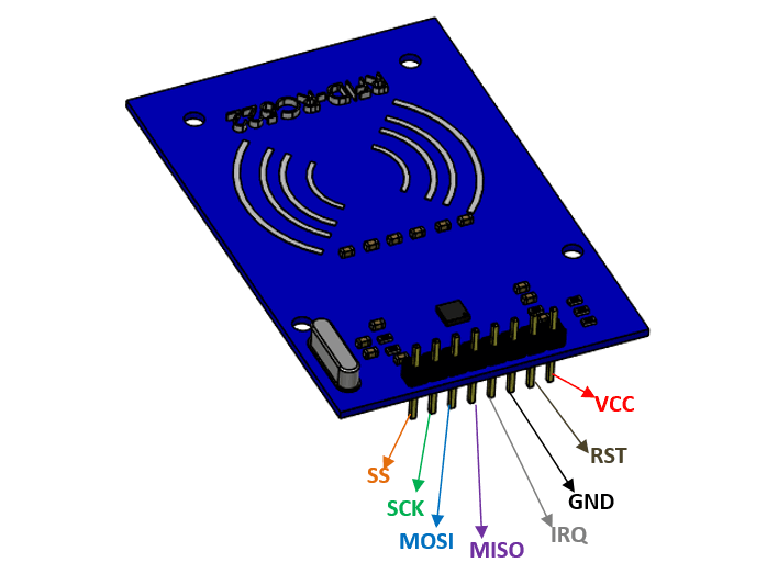
- Vcc: In order to run the module the allowable voltage is up to 3.3V. Unlike most of the modules RC522 doesn’t accept 5V as an input.
- GND: As we know that in order to make a closed circuit GND terminal is required.
- IRQ (Interrupt Request): It goes high when a RFID tag comes into the proximity of RFID reader. It helps in interrupting the microcontroller to pause (or perform) the task as designed by the engineer.
- RST (Reset): It is an active low pin. When logic 0 is applied to the pin, the RFID reader will be switched OFF.
- MISO (Master In Slave Out): In a SPI (Serial Peripheral Interface), multiple peripheral devices (Slave) are being communicated with the microcontroller (Master) quickly. So MISO is used to send the data to the master (microcontroller) from the salve (peripheral device).
- MOSI (Master Out Slave In): Similar to the MISO, using MOSI pin Master can send the data to the peripheral devices.
- SCK (Serial Clock): In order to synchronize the data transmission between the master and slave SCK pin is used which generates clock pulses.
- SS (Slave Select): In case if the slave devices are more than one, the SS can be used to select the desired device when required.
Features of RFID Module
- Host interfaces supported are SPI, RS232 serial UART and I2C.
- Typical operating distance in Read/Write mode is up to 50 mm based on the size of antenna size and tuning.
- Reset with low power function for power efficiency.
- Interrupt modes are flexible for interfacing with microcontroller when multiples devices have to be connected.
- 2.5 V to 3.3 V operating voltage.
- Internal self test for testing the device by itself when powered ON to check whether the system is working as expected or not.
Important Note: The features and pin description discussed here is applicable only to RC522 RFID module. Please use this link to know more about other RFID modules.
Applications of RFID
- Used in office/schools for attendance management.
- Used for inventory tracking.
- Used to avoid fraudulent/stolen products from malls and super markets.
- In constructions industries RFID technology can be used to manage materials.
- Used in Real Time Location systems (RTLS) for tracking the location of a particular asset or an employee.
- Used to lock and unlock the doors.
- And many more.


