TIP127 PNP Darlington Transistor Pinout, Specifications, Equivalent & Datasheet
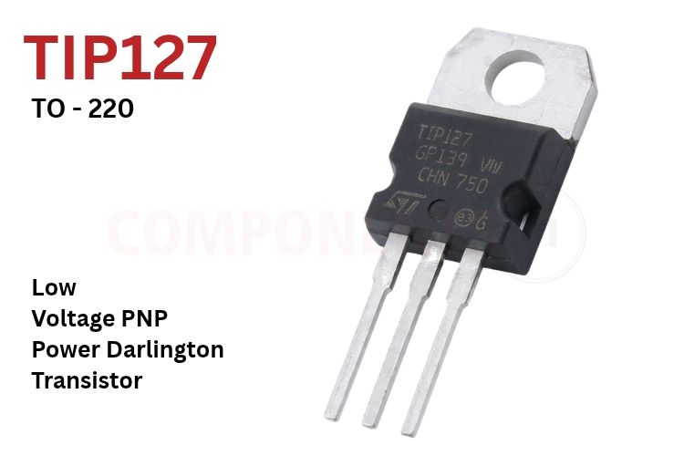
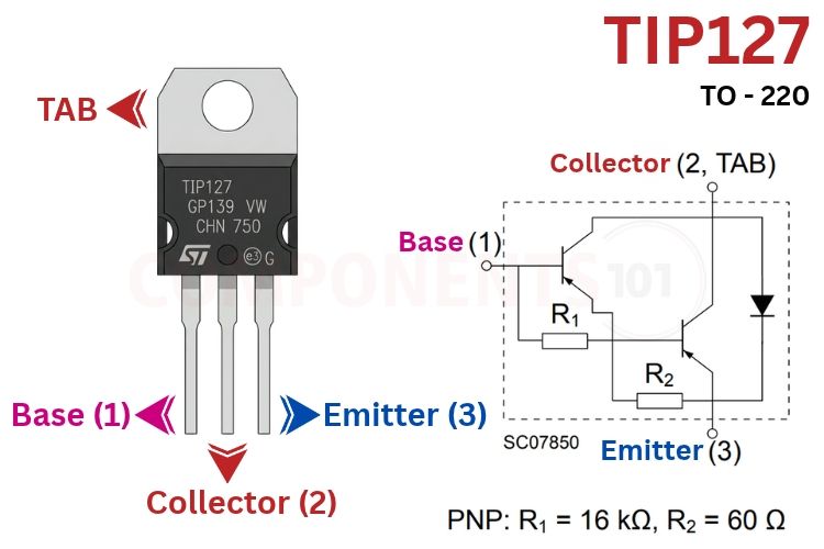
The TIP127 is a general-purpose medium-power PNP epitaxial-base silicon power Darlington transistor housed in the 3-lead TO-220 (TO-220AB) plastic package. The TIP127 transistor is a PNP Darlington power transistor device that features a high collector-emitter breakdown voltage rating of -100V (VCEO), a continuous collector current rating of -5.0 A (IC), a peak pulsed current capability of -8.0 A (ICM), and an ultra-high DC gain (hFE ≥ 1000 at -3.0 A).
Inside the TO-220 encapsulation, the TIP127 integrates a monolithic two-stage Darlington pair, two built-in base-emitter bleed resistors (R1 = 16 kΩ, R2 = 60 Ω), and an anti-parallel freewheeling damper diode across the collector and emitter terminals. The TIP127 serves as the direct complementary PNP partner to the widely used TIP122 NPN Darlington transistor. The TIP127 is an essential discrete component in 24V industrial solenoid drivers, high-side DC motor switches, Class AB audio power amplifiers, relay actuators, and linear power regulators driven directly from 3.3V or 5V microcontrollers.
TIP127 Pinout Configuration
Looking directly at the front-facing side of the TO-220 package with the leads oriented downward, the pinout configuration is structured as follows:
| Pin Number | Pin Name | Description |
| 1 | Base (B) | Controls the PNP Darlington conduction state. Sinking current out of the base turns the transistor ON. |
| 2 | Collector (C) | High-current power terminal connected to the load. Internally bonded to the metallic heatsink tab. |
| 3 | Emitter (E) | Power supply terminal connected to the positive DC power supply rail (+VCC) in typical high-side switching circuits. |
| Tab | Collector (C) | Metallic mounting tab electrically connected to Pin 2 Collector for efficient thermal dissipation. |
TIP120 Series Voltage Grade Differences
The TIP120/TIP125 product family is produced in three distinct breakdown voltage grades. The final numeral in the part number designates the maximum collector-emitter blocking voltage:
| Model Variant | Polarity | Collector-Emitter Voltage (VCEO) | Continuous Collector Current (IC) | Typical Voltage Suitability |
| TIP120 / TIP125 | NPN / PNP | 60V / -60V | 5.0 A | Standard 12V automotive and consumer portable electronics. |
| TIP121 / TIP126 | NPN / PNP | 80V / -80V | 5.0 A | 24V to 36V industrial control systems and solenoid drivers. |
| TIP122 / TIP127 | NPN / PNP | 100V / -100V | 5.0 A | Premium 100V variant; universally replaces TIP120, TIP121, TIP125, and TIP126. |
*Note: Because the TIP127 provides the highest -100V breakdown margin at the same price point and physical TO-220 footprint, circuit designers and repair technicians universally standardize on the TIP127 as a universal replacement across all lower-voltage PNP Darlington variants.
TIP127 Key Features & Specifications
- Transistor Polarity / Type: Monolithic PNP Epitaxial-Base Power Darlington Transistor
- Collector-Emitter Breakdown Voltage (VCEO): -100V (IB = 0)
- Collector-Base Breakdown Voltage (VCBO): -100V (IE = 0)
- Emitter-Base Reverse Voltage (VEBO): -5.0 V (IC = 0)
- Continuous Collector Current (IC): -5.0 A
- Peak Pulsed Collector Current (ICM): -8.0 A
- Continuous Base Current (IB): -0.12 A (120 mA)
- Total Power Dissipation (PD): 65W at case temperature TC ≤ 25°C (2.0W at ambient TA ≤ 25°C in free air)
- Collector-Emitter Saturation Voltage (VCE(sat)): -2.0V max at IC = -3.0 A, IB = -12 mA; -4.0V max at IC = -5.0 A, IB = -20 mA
- Base-Emitter On Voltage (VBE(on)): -2.5V max at IC = -3.0 A, VCE = -3.0 V
- DC Current Gain (hFE): 1000 min at IC = -0.5 A, VCE = -3.0 V; 1000 min (typical 1000 to 5000) at IC = -3.0 A, VCE = -3.0 V
- Turn-On Time (ton): 0.5 μs typical at IC = -3.0 A, IB1 = -12 mA
- Turn-Off Time (toff): 2.5 μs typical at IC = -3.0 A, IB1 = -12 mA
- Thermal Resistance (RthJC): 1.92 °C/W (Junction-to-Case)
- Thermal Resistance (RthJA): 62.5 °C/W (Junction-to-Ambient)
- Operating Junction Temperature (TJ): -65°C to +150°C
- Storage Temperature Range (Tstg): -65°C to +150°C
- Integrated Components: Internal bleed resistors (R1 = 16 kΩ, R2 = 60 Ω) and anti-parallel freewheeling damper diode
- Package Type: TO-220 (Type H / TO-220AB Through-Hole)
| Electrical Parameter | Symbol | Test Conditions | Min | Max | Unit |
| Collector-Emitter Sustaining Voltage | VCEO(sus) | IC = -30 mA, IB = 0 | -100 | - | V |
| Collector Cut-off Current | ICEO | VCE = -50 V, IB = 0- | - | -0.5 | mA |
| Collector Cut-off Current | ICBO | VCB = -100 V, IE = 0 | - | -0.2 | mA |
| Emitter Cut-off Current | IEBO | VEB = -5.0 V, IC = 0 | - | -2.0 | mA |
| Collector-Emitter Saturation Voltage | VCE(sat) | IC = -3.0 A, IB = -12 mA | - | -2.0 | V |
| Collector-Emitter Saturation Voltage | VCE(sat) | IC = -5.0 A, IB = -20 mA | - | -4.0 | V |
| Base-Emitter On Voltage | VBE(on) | IC = -3.0 A, VCE = -3.0 V | - | -2.5 | V |
| DC Current Gain | hFE | IC = -0.5 A, VCE = -3.0 V | 1000 | - | - |
| DC Current Gain | hFE | IC = -3.0 A, VCE = -3.0 V | 1000 | - | - |
| Turn-On Time | ton | IC = -3.0 A, IB1 = -12 mA | - | - | μs |
| Turn-Off Time | toff | IC = -3.0 A, IB1 = -12 mA | - | - | μs |
*Note: Complete Technical Details can be found in the TIP127 datasheet given at the end of this page.
TIP127 Transistor Equivalent & Alternative Components
| Equivalent Part | Polarity | Key Ratings | Description & Compatibility Notes |
| TIP122 | NPN | 100V, 5A, 65W, TO-220 | Exact complementary NPN partner for push-pull audio and H-bridge motor drives. |
| TIP125 | PNP | -60V, -5A, 65W, TO-220 | Lower-voltage sibling; TIP127 is a 100% pin-compatible upgrade with 40V higher safety margin. |
| TIP126 | PNP | -80V, -5A, 65W, TO-220 | Intermediate-voltage sibling; TIP127 serves as direct drop-in replacement. |
| BD650 | PNP | -100V, -8A, 62.5W, TO-220 | European higher-current alternative; handles up to 8A continuous load current. |
| BD652 | PNP | -120V, -8A, 62.5W, TO-220 | 120V, 8A power Darlington in standard TO-220 footprint for heavy 48V systems. |
| BDT64C | PNP | -100V, -10A, 125W, TO-220 | Heavy-duty 10A 100V PNP Darlington matching the TIP127 voltage threshold. |
| 2N6042 | PNP | -100V, -8A, 75W, TO-220 | High-reliability 8A 100V PNP Darlington power transistor. |
| TIP42C | PNP | -100V, -6A, 65W, TO-220 | Standard discrete BJT (non-Darlington). Lower VCE(sat) (1.5V) but requires 10x higher base drive current. |
Brief Description of TIP127
The TIP127 is an iconic discrete power semiconductor in modern power electronics. As a PNP bipolar Darlington transistor, current enters the Emitter (Pin 3) and exits through the Collector (Pin 2). Conduction is initiated when current is drawn out of the Base (Pin 1), requiring the base to be pulled at least 1.4V lower than the positive supply rail.
Key operational characteristics of the TIP127 include:
1. Monolithic Darlington Current Gain Multiplication: The internal pair cascades driver transistor Q1 into output power transistor Q2. The effective current gain is approximately the product of both stages (hFE_total ≈ hFE1 × hFE2). With individual gains between 30 and 80, the composite structure guarantees an overall current gain exceeding 1000 to 5000. This enables a microcontroller circuit providing only 5 mA to 12 mA of base current to switch multi-ampere loads up to 5.0 A without requiring specialized gate driver ICs.
2. Integrated Base-Emitter Stabilization Resistors: Discrete high-gain Darlington circuits often suffer from thermal instability and prolonged turn-off delays due to stored minority carrier charge. The TIP127 integrates two diffused resistors: R1 (16 kΩ) across the driver base-emitter bleeds off high-temperature leakage current (ICBO), preventing thermal runaway; R2 (60 Ω) across the power stage base-emitter provides a rapid recombination discharge path, shortening turn-off time to 2.5 μs.
3. Built-in Inductive Damper Diode: A monolithic anti-parallel diode is diffused across the collector and emitter terminals (Anode to Collector, Cathode to Emitter). In inductive switching circuits, when the transistor cuts off, the collapsing magnetic field of coils, motors, or solenoids generates a large inductive back-EMF spike. The integrated diode provides a bypass clamp path that helps protect the transistor junctions from destructive overvoltage breakdown.
4. Complementary Push-Pull Pairing with TIP122: Symmetrical Class-AB audio power amplifiers and bidirectional full-bridge (H-bridge) motor drivers require closely matched NPN and PNP characteristics. The TIP127 is specifically processed to mirror the electrical gain curves, saturation voltages, and switching speeds of the TIP122 NPN Darlington.
5. TO-220 Mounting Tab & Thermal Isolation: The metallic mounting tab of the TO-220 package is internally bonded to Pin 2 Collector. In high-side switching circuits, Pin 2 sits at the positive rail voltage when the load is active and floats near 0V when OFF. If mounting the TIP127 to an earthed metal chassis or a shared heatsink, an insulating sil-pad or mica washer along with a nylon shoulder bushing must be used to prevent short-circuiting the power rail.
TIP127 Datasheet
The complete original manufacturer technical specifications, safe operating area (SOA) curves, and saturation voltage performance plots are available in the official PDF TIP127 Datasheet.
TIP127 Applications
- Solenoid & Valve Drivers: Actuating pneumatic and hydraulic directional valves in factory automation and agricultural irrigation machinery.
- High-Side DC Motor Controllers: PWM-controlled high-side switching legs in industrial conveyor drives, motorized dampers, and robotic arms.
- Class AB Audio Power Amplifiers: High-voltage complementary output stages paired with TIP122 for 50W to 80W Class-AB audio power amplifiers.
- High-Power Relay & Contactor Drivers: Switching high-current contactor coils and heavy automotive relays without secondary driver ICs.
- Linear DC Voltage Regulators: Series pass power element in positive linear bench power supplies and low-noise laboratory voltage regulators up to 60V output.
- Battery Disconnect & Reverse Polarity Protection: Power gating and emergency battery transfer switches in 24V/48V backup battery systems.
2D Model and Component Dimensions
For PCB layout engineers creating footprints in EDA design tools (KiCad, Altium Designer, Eagle, EasyEDA), the physical dimensions for the standard TO-220 (Type H / TO-220AB) package are detailed below:
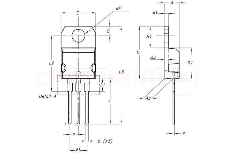
| Parameter Symbol & Description | Minimum (mm) | Typical (mm) | Maximum (mm) |
| A (Package Thickness / Total Depth) | 4.40 | 4.45 | 4.50 |
| A1 (Heatsink Tab Thickness) | 1.22 | - | 1.32 |
| A2 (Base to Seating Plane) | 2.49 | 2.59 | 2.69 |
| A3 (Step Thickness to Tab) | 1.17 | 1.27 | 1.37 |
| b (Lead Width, X3) | 0.78 | - | 0.87 |
| b2 (Upper Lead Width Section, Pins 1 & 3) | 1.25 | - | 1.34 |
| b4 (Upper Lead Width Section, Pin 2) | 1.20 | - | 1.29 |
| c (Lead Thickness) | 0.49 | - | 0.56 |
| D (Total Package Body Height) | 15.40 | 15.50 | 15.60 |
| D1 (Plastic Mold Case Body Height) | 9.05 | 9.15 | 9.25 |
| E (Total Package Body Width) | 10.08 | 10.18 | 10.28 |
| e (Lead Pitch / Pin Spacing) | 2.44 | 2.54 | 2.64 |
| e1 (Total Pin 1 to Pin 3 Spacing) | 4.98 | 5.08 | 5.18 |
| H1 (Heatsink Tab Height Above Body) | 6.25 | 6.35 | 6.45 |
| L (Lead Length Below Seating Plane) | 13.20 | 13.40 | 13.60 |
| L1 (Transition Lead Length Below Mold Body) | 3.50 | 3.70 | 3.90 |
| L2 (Hole Center to Lead Shoulder) | 16.30 | 16.40 | 16.50 |
| L3 (Overall Package Length with Leads) | 28.70 | 28.90 | 29.10 |
| ØP (Mounting Hole Diameter) | 3.75 | 3.80 | 3.85 |
| Q (Tab Top to Hole Center Distance) | 2.70 | 2.80 | 2.90 |