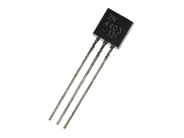
2N4403 - PNP Transistor
2N4403 is a general purpose PNP transistor used for low power switching and amplifier applications. The NPN complementary for the device is 2N4400, 2N4401.
Pin Configuration
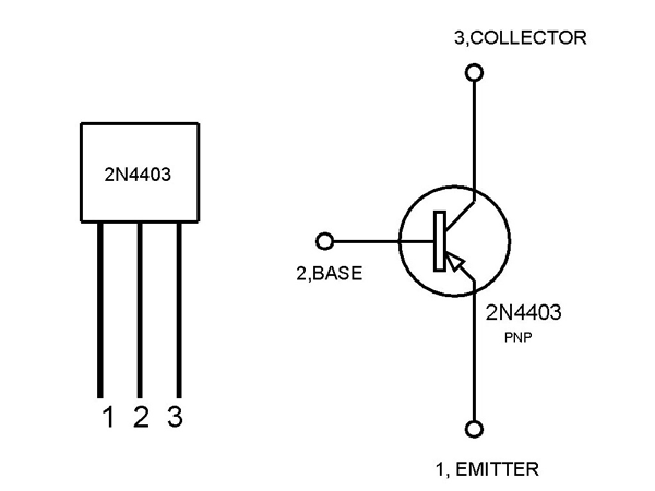
2N4403 has three pins like any other transistor namely EMITTER, BASE and COLLECTOR.
|
Pin |
Name |
Description |
|
1 |
Emitter |
Normally connected to Power |
|
2 |
Base |
Base is used for triggering transistor ON and OFF |
|
3 |
Collector |
Normally connected to Load |
2N4403 Features and Specifications
- Silicon planar epitaxial transistor
- Pb−free packages are available
- With DC Current Gain (hFE) up to 300
- Maximum voltage across collector and emitter: 40V
- Maximum current allowed trough collector: 600mA
- Maximum voltage across collector and base: 40 V
- Maximum current allowed trough base: 50mA
- Maximum voltage across base and emitter: 5V
- Operating temperature range: -55ºC to +150ºC
- Maximum power dissipation : 0.31 W
Similar Transistors
NTE159, 2SA1015GR, 2N5401, 2N3905
2N4403 Transistor Overview
2N4403 is basically used when you want a simple switching device for low power loads. The component is cheap and easy to work with so it is best suited when choosing a random switching device. 2N4403 can also used as a basic power amplifier and its application include amplifying low power signals.
How to use 2N4403 Transistor
2N4403 can be used in any general transistor application circuits but for understanding the working let us consider a simple 2N4403 switching circuit as shown below.
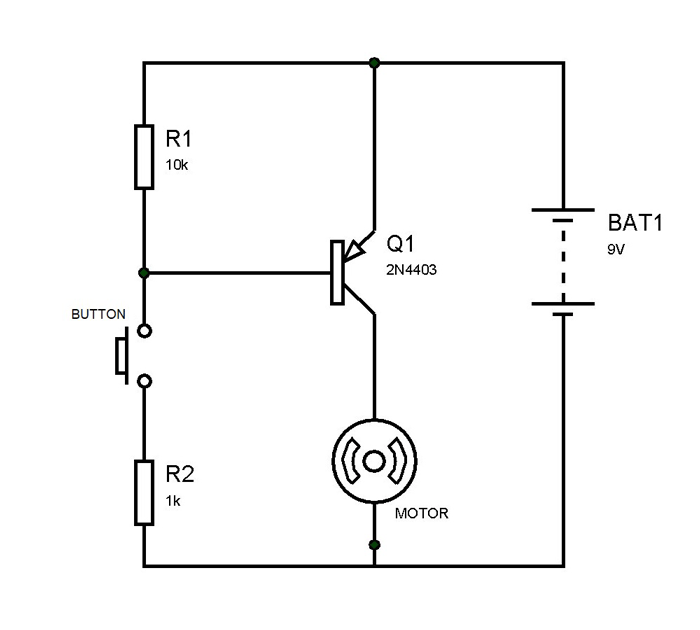
In the above circuit we are using 2N4403 as a simple switching device and a small motor as the load. The small button here is for providing the trigger to the transistor and can be removed to leave simple contacts to touch. With the gain of the transistor a simple touch can trigger it. The 10KΩ resistor is for limiting the current to base and to avoid breaching maximum voltage allowed at the base. The 1KΩ resistor is for limiting the current flowing out of base to ground.
Working
Under no interference there will be a positive voltage appearing at the base of the PNP transistor and based on working on PNP transistor having a positive voltage at gate leaves transistor in high resistance state. Based on the characteristic of a PNP transistor the current needs to flow out of base not in to the base for it to turn ON. So when a positive voltage appears at base only leakage current flows through transistor and all the battery voltage (BAT1) appears across it. As shown in below graph a current of 10mA needs to flow out of base for a flow of 100mA collector current and switching ON the transistor completely.
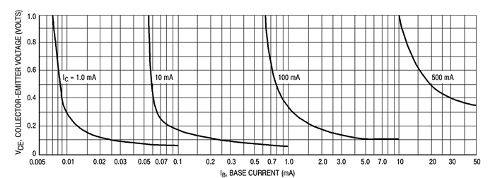
When the button is pressed the base of the transistor will be connected to the ground and a loop will be formed for the current to flow from the base to the ground. With this current flow the transistor gets turned ON and a current flows through the collector followed by motor. And so when the button pressed current flows though the motor turning it ON.
After the button opened again the base current flow will be cutoff there by turning OFF the motor. Hence we have used 2N4403 as a simple switching device and in the same way we can use this transistor in all other application circuits.
Applications
- Simple switching applications
- Microphone pre-amplifiers
- Lighting systems
- Relay drivers
- Audio Amplifiers
- Signal Amplifiers
2D-Model
