1.54inch e-Paper Module
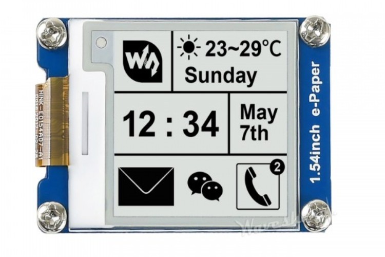
The 1.54" ePaper display module is a practical choice for projects that require displays with low power consumption and good readability. This module uses ePaper technology to show black-and-white content, which can stay on the screen even when there's no power, thanks to its bi-stable nature. It has a resolution of 200x200 pixels, allowing it to display clear and crisp text and images. Compared to LCD, OLED, and LED displays, ePaper offers superior visibility in bright lighting and significantly lower power usage, making it especially useful for applications where power efficiency and long display durations are critical. The module is easy to interface with, needing only a few control lines to connect to popular microcontrollers like the Arduino and Raspberry Pi. It also features partial refresh capabilities, which helps save power by only updating parts of the screen that need changes. This makes it suitable for applications like portable devices, e-readers, and any other system where power efficiency is important.
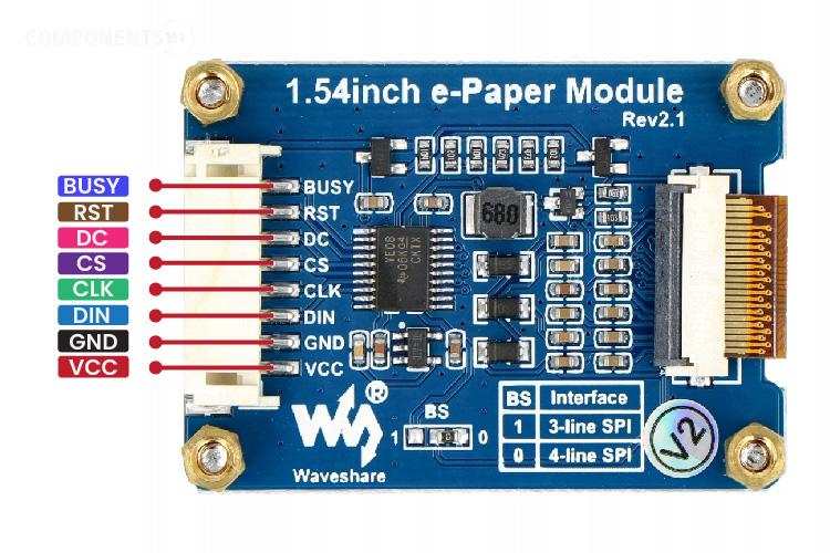
ePaper Display Module Pinout
The pinout for the Waveshare 1.54" ePaper display module typically includes the following connections, which are essential for interfacing the display with a microcontroller. The Module uses an SPI bus for interfacing with the microcontroller.
| Pin Name | Description | Connection |
| VCC | Power supply (3.3V) | Connect to 3.3V on the microcontroller |
| GND | Ground | Connect to the ground on the microcontroller |
| DIN | Data Input, SPI MOSI (Master Out Slave In) | Connect to the MOSI pin on the microcontroller |
| CLK | Clock, SPI clock | Connect to SCK (Serial Clock) pin on the microcontroller |
| CS | Chip Select, activates the module for SPI communication | Connect to a free digital I/O pin set as output on the microcontroller |
| DC | Data/Command pin, differentiates data and command signals | Connect to another digital I/O pin on the microcontroller |
| RST | Reset, resets the module | Connect to another digital I/O pin on the microcontroller |
| BUSY | Busy state output, indicates processing state | Connect to a digital I/O pin to monitor module status |
ePaper Display Module Parts Marking
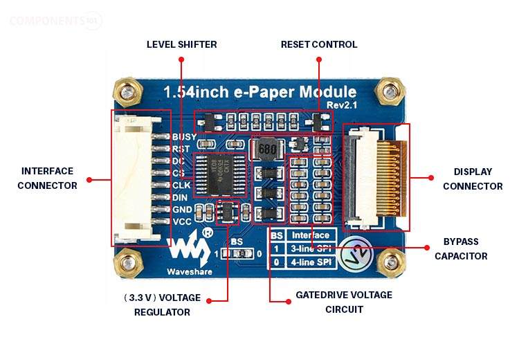
The circuitry includes a power supply section, which typically involves a voltage regulator ensuring stable 3.3V output from varied input sources. There are also discrete components like resistors and capacitors that stabilise the operation and filter noise from the power supply.
The circuit design also includes a reset circuit controlled by the RST pin, which ensures the display starts in a known state during power-ups or after errors. The BUSY pin is part of a feedback mechanism used by the microcontroller to ascertain the module's status, preventing data from being sent when the module is busy updating the display.
ePaper Display Module Specifications
- Operating voltage: 3.3V/5V
- Interface: 3-wire SPI, 4-wire SPI
- Outline dimension: 48mm × 33mm
- Display size: 27.6mm × 27.6mm
- Dot pitch: 0.138 × 0.138
- Resolution: 200 × 200
- Display color: black, white
- Grey level: 2
- Partial refresh time: 0.3s
- Full refresh time: 2s
- Refresh power: 26.4mW(typ.)
- Standby power: <0.017mW
- Viewing angle: >170°
- High contrast
- High reflectance
- Ultra wide viewing angle
- Ultra low power consumption
- Pure reflective mode
- Bi-stable display
- Commercial temperature range
- Landscape, portrait modes
- Hard-coat antiglare display surface
- Ultra Low current deep sleep mode
- On-chip display RAM
- Low voltage detect for supply voltage
- High voltage ready detect for driving voltage
- Internal temperature sensor
- 10-byte OTP space for module identification
- Waveform stored in On-chip OTP
- Serial peripheral interface available
- On-chip oscillator
- On-chip booster and regulator control for generating VCOM, Gate and Source driving voltage
Alternate Display Solution
If you are looking for a display for your project you could also check out the following type of display:
16x2 LCD, 7-segment display, TM1637 4-digit display module, 2.4” TFT, 128x64 LCD, LED Bar Display, OLED Display, Nokia 5110 LCD, MAX7219 Dotmatrix Display Module
1.54” ePaper Display Module Circuit Diagram
Here is the circuit diagram for the 1.54” ePaper display module.
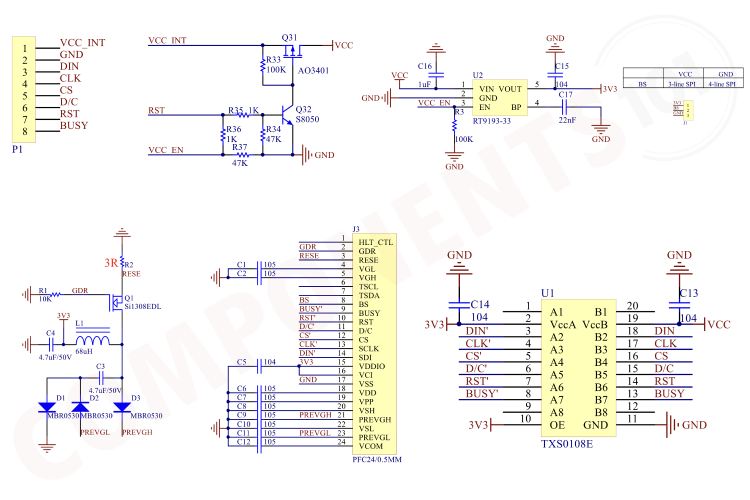
The module its self-included all the voltage generation circuits along with a level shifter. The transistors Q31 and Q31 creates a reset circuit, which can used to reset the display using the RST pin. The display panel itself is powered from a 3.3V line which is generated by the RT9193-33 LDO. Then ePaper display panel needs very high voltage signals for switching, This is generated using the gate drive voltage circuitry built around the MOSFET Q1 and inductor L1 along with some diodes and a capacitor. This circuit is responsible for both positive and negative gate drive voltages. Next, the panel itself is connected to the module using a 24-pin FPC cable. You can also see all the necessary bypass capacitors around it. Then for the level shifting, we are using the TXS0108E 8-Channel Bi-Directional Logic Level Converter from Texas Instruments.
How does ePaper Displays Work?
E-paper technology, commonly used in devices like e-readers and digital signage, mimics the appearance of ordinary ink on paper. It reflects light like paper, making it easy on the eyes and readable in bright light, unlike traditional backlit displays. The working principle behind the ePaper display is known as Microcapsule Electrophoresis. Here's how it works:
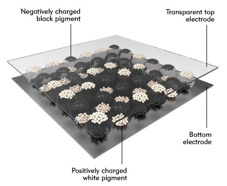
The most common e-paper technology involves millions of tiny microcapsules, about the diameter of a human hair, embedded in a thin layer. Each microcapsule contains positively charged white particles and negatively charged black particles suspended in a clear fluid.
Here is how the pixel manipulation is happening. When a positive electric field is applied to a particular capsule, the white particles move to the top, making the surface appear white at that spot. Conversely, when a negative electric field is applied, the black particles come to the top, making the surface appear black.
This selective application of electrical fields allows for the creation of images and text as patterns of black and white across the screen.
One of the key features of e-paper is that it is bi-stable. This means that the text or images on the display will remain visible without electricity once set. The display only requires power during the change of content, not to maintain the display itself. This results in a very low power consumption compared to other display technologies.
Although the most basic e-paper displays are monochrome (black and white), there are versions capable of displaying grayscale or even color. For grayscale, varying the voltage applied allows different shades of grey to appear due to the partial movement of black and white particles. Color e-paper displays work by adding a color filter on top of the microcapsules or by using colored particles within the capsules themselves.
Advantages of ePaper Display Over Traditional Displays
Low Power Consumption: Only use power when updating the screen.
Visibility and Eye Comfort: Highly readable in direct sunlight and gentle on the eyes due to its non-emissive nature.
Paper-like Display: Provides a natural, paper-like look which does not emit light but rather reflects ambient light.
E-paper has revolutionised certain applications like e-readers and digital signage due to these characteristics, providing a digital yet natural reading and viewing experience.
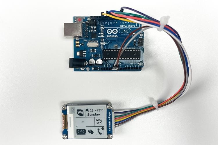
Interfacing 1.54” ePaper Display with Arduino
For interfacing the 1.54” ePaper Display with Arduino, follow the connections as per the circuit diagram below.
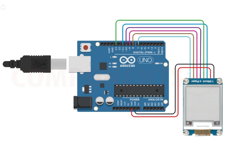
Connects the module's VCC and GND pins to the 5V and GND pins of the Arduino. Then connect the DIN, CLK, CS, DC, RST and BUSY pins of the modules to Arduino pins D11, D13, D10, D9, D8 and D7.
Once the connections are made download the 1.54" ePaper Display Images Demo Code and extract it to a folder. In the extracted folder open the Arduino folder and then open the epd1in54_V2.ino sketch file in Arduino IDE. Select the proper board and upload the compiled code to the Arduino board. To learn more about ePaper display interfacing please check out the Interfacing 1.54-inch E-Paper Display with Arduino UNO article.
How to Display Images
To display images first you need to convert the images in to an array format. For that use the online tool image2cpp. Open the page and select your image using choose file option.
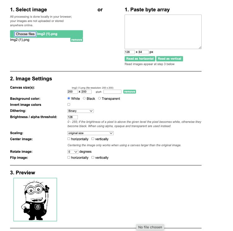
It will automatically detect all the default settings. In the output section select Arduino code single bitmap, and press generate button to generate e the array.
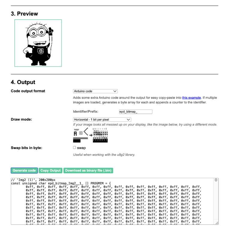
Copy this array and paste it into the imagedata.cpp file. Next open up the imagedata.h file and add a new constant in the following format
extern const unsigned char IMG1[];
Where, replace IMG1 with the name of the array. Now in the code you can display this image using the following line.
epd.DisplayPartBaseImage(IMG1);
paint.SetWidth(200);
paint.SetHeight(200);
epd.DisplayPartFrame();
You can replace the array name and its height and width. If you are using a smaller image and you want to specify the location you can use the SetFrameMemoryPartial( const unsigned char* image_buffer, int x, int y, int image_width, int image_height ); function prior to calling DisplayPartFrame function.
Applications
- E-Readers
- Digital Signage
- Smart Home Devices
- Wearable Technology
- Shelf Labels in Retail
- Medical Devices
- Mobile Devices
- Electronic Badges and ID Cards
- Art and Design
- Transportation
Facing problems interfacing the ePaper Module?
Here are some troubleshooting tips for you.
My display is not powering on. What should I check?
Ensure the display is connected to a stable 3.3V source. Verify the connections at the VCC and GND pins. Confirm that all pin connections are secure and correctly aligned according to the display's pinout.
The display is powered but shows no content. What could be wrong?
Check the DIN, CLK, and CS connections for proper SPI communication setup. Make sure that the microcontroller is running the correct driver code for the ePaper display. The initialization sequence in the code is crucial.
The content on the display is partial or incorrect. How do I fix this?
Ensure that your code includes a refresh command after sending data to the display. Verify that the DC pin is correctly controlled by your microcontroller to switch between data and command.
1.54” ePaper Display Module Dimensions
Here are the dimensions for the 1.54” ePaper matrix display module. It will come in handy if you want to create a custom footprint or an enclosure.
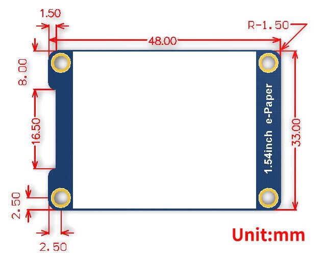
The module comes with dimensions of 48mmx33mm. The module also features four mounting holes with provision for M3 screws.


