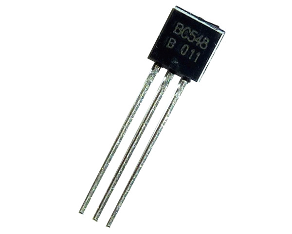
BC548 - NPN Transistor
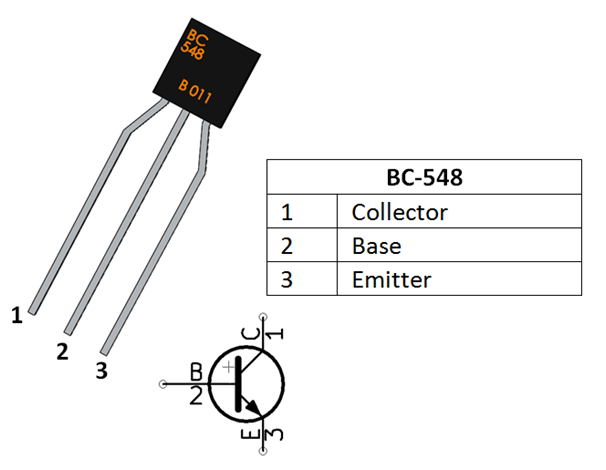
BC548 Pin Configuration
|
Pin Number |
Pin Name |
Description |
|
1 |
Collector |
Current flows in through collector |
|
2 |
Base |
Controls the biasing of transistor |
|
3 |
Emitter |
Current Drains out through emitter |
BC548 Transistor Features
- Bi-Polar NPN Transistor
- DC Current Gain (hFE) is 800 maximum
- Continuous Collector current (IC) is 500mA
- Emitter Base Voltage (VBE) is 5V
- Base Current(IB) is 5mA maximum
- Available in To-92 Package
Note: Complete Technical Details can be found at the BC548 transistor datasheet give at the end of this page.
Alternate for BC548
BC548 Equivalent Transistors
BC549, BC636, BC639, 2N2222 TO-92, 2N2222 TO-18, 2N2369, 2N3055, 2N3904, 2N3906, 2SC5200
Brief Description of BC548
BC548 is a NPN transistor so the collector and emitter will be left open (Reverse biased) when the base pin is held at ground and will be closed (Forward biased) when a signal is provided to base pin. BC548 has a gain value of 110 to 800, this value determines the amplification capacity of the transistor. The maximum amount of current that could flow through the Collector pin is 500mA, hence we cannot connect loads that consume more than 500mA using this transistor. To bias a transistor we have to supply current to base pin, this current (IB) should be limited to 5mA.
When this transistor is fully biased, it can allow a maximum of 500mA to flow across the collector and emitter. This stage is called Saturation Region and the typical voltage allowed across the Collector-Emitter (VCE) or Base-Emitter (VBE) could be 200 and 900 mV respectively. When base current is removed the transistor becomes fully off, this stage is called as the Cut-off Region and the Base Emitter voltage could be around 660 mV.
BC548 as Switch
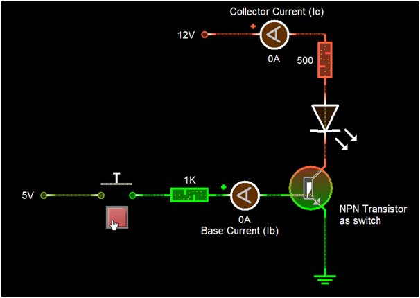
When a transistor is used as a switch it is operated in the Saturation and Cut-Off Region as explained above. As discussed a transistor will act as an Open switch during Forward Bias and as a closed switch during Reverse Bias, this biasing can be achieved by supplying the required amount of current to the base pin. As mentioned the biasing current should be maximum of 5mA. Anything more than 5mA will kill the Transistor; hence a resistor is always added in series with base pin to limit the current. The value of this resistor (RB) can be calculated using below formula.
RB = VBE / IB
Where, the value of VBE should be 5V for BC548 and the Base current (IB depends on the Collector current (IC). The value of IB should not exceed 5mA.
BC547 as Amplifier
A Transistors acts as an Amplifier when operating in Active Region. It can amplify power, voltage and current at different configurations.
Some of the configurations used in amplifier circuits are
- Common emitter amplifier
- Common collector amplifier
- Common base amplifier
Of the above types common emitter type is the popular and mostly used configuration. When used as an Amplifier the DC current gain of the Transistor can be calculated by using the below formulae
DC Current Gain = Collector Current (IC) / Base Current (IB)
Applications
- Driver Modules like Relay Driver, LED driver etc..
- Amplifier modules like Audio amplifiers, signal Amplifier etc..
- Darlington pair
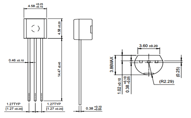
2D-Model and Dimensions
If you are designing a PCB or Perf board with this component then the following picture from the Datasheet will be useful to know its package type and dimensions.