TB6600 Stepper Motor Driver Module
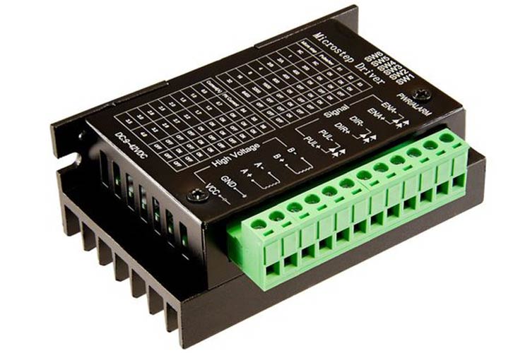
TB6600 Stepper motor driver is a cheap and effective device which provides microstepping ability to a stepper motor. It is suitable for driving 2 phase and 4 phase hybrid stepper motors. The motor driver compatible with any microcontroller providing a 5V signal.
Features and Specifications of TB6600 Stepper Motor Driver Module
This section mentions some of the applications of TB6600 stepper motor driver.
- Operating voltage: 9-40V DC
- Output Current: 0.7-4.0A
- Pulse input frequency up to 20kHz
- 5V levels input signal
- 200-6400 pulse per revolution
- Logic signal current: 8-15mA
- Output current selectable in 8-steps via DIP switches
- Suitable for 2 and 4 phase motors
- Over current and over heat protection
- Inputs are optically isolated
Alternatives for TB6600 Stepper Motor Driver Module
MKS-LV8729-OC, TB67S109, DRV8825, A4988, TMC2208
Note: Complete technical information can be found in the TB6600 Datasheet linked at the bottom of this page.
Pin Configuration of TB6600 Stepper Motor Driver Module
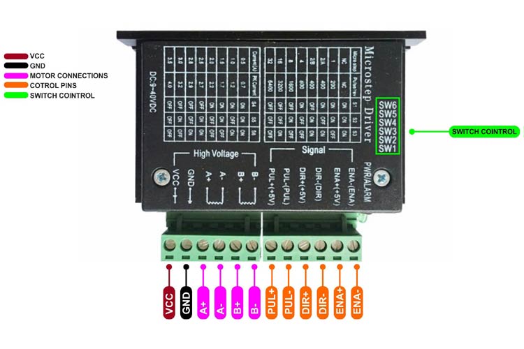
The table below describes all the pins on the stepper motor driver along with their functions:
|
Pin Type |
Pin Description |
|
ENA-(ENA) |
Enable pin(-) |
|
ENA+(+5V) |
Enable(+5V) |
|
DIR-(DIR) |
Direction(-) |
|
DIR+(+5V) |
Direction(+5V) |
|
PUL-(PUL) |
Pulse(-) |
|
PUL+(+5V) |
Pulse(+5V) |
|
B- |
Stepper motor 1 coil wire |
|
B+ |
Stepper motor 1 coil wire |
|
A- |
Stepper motor 2 coil wire |
|
A+ |
Stepper motor 2 coil wire |
|
GND |
Ground |
|
VCC |
Input Voltage(9-40V) |
Connecting TB6600 Stepper Motor Driver Module with a MCU/MPU
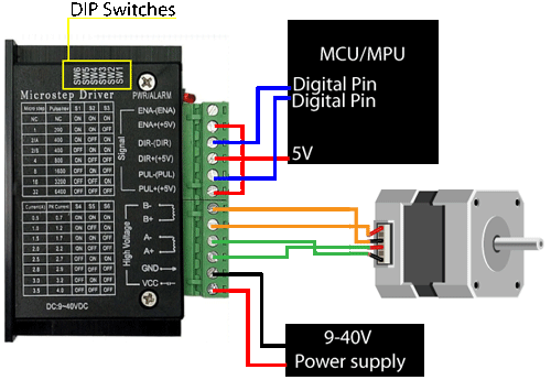
Connecting the TB6600 motor driver module to a stepper motor and the microcontroller is pretty easy. You would just need a few jumper wires and a 9-40V power supply unit.

The motor driver, as seen in the image, has two sections; high voltage and the signal. High voltage part consists of wiring of the stepper motor and the power supply, whereas the signal part consists of connecting the module to the MCU/MPU. The PUL(+5V), DIR(+5V), (ENA+5V) pins are shorted and connected to the 5V supply of the MCU/MPU. The DIR- and PUL- are to be connected to the digital pins of the MCU/MPU nd the ENA- pin has to be left floating. Once you have figured out the paired coil wires of the stepper you can connect it to the Port A and Port B. At the end, you can plug the motor driver to a power supply unit to GND and VCC pins.
Note: The stepper motor has 4 wires; and the motor consists of two coils which help rotate the shaft. It is important to find the pair of the wires internally connected to each coil. There are 2 methods to check that:
- Continuity method: Take a multimeter and put it on the continuity check mode. Try connecting two wires to the probes of the multimeter. If the multimeter gives a sound output when two wires touch the probes, this means that they are of the same coil and be used to connect to a single port(A+/A- or B+/B-). If the multimeter does not beep, try connecting the other wire to one of the probe and try it till you find the pair of wires.
- Variable torque method: If you do not have a multimeter, you can use this method to find out the pair of wires. Just connect two of the 4 wires from the stepper motor and try spinning the rotor shaft. If the two wires are in the same coil or loop, you would notice an increased torque along with some click sound from motor.
Applications of TB6600 Stepper Motor Driver Module
Below are some of the applications of the TB6600 Stepper Motor Driver Module:
- Used for positioning stepper motors
- Used in CNC machines
- Used in 3D printers
- Used in antennas
2D Model of TB6600 Stepper Motor Driver Module
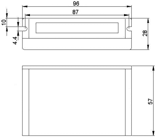
The 2D model of the TB6600 stepper motor driver along with its dimensions in millimeters are shown in the image below. These dimensions can be used while designing custom footprints to be used for PCB designing or CAD modelling.

Note: The dimensions are in millimeters.


