Si4703 - SparkFun FM Tuner Module
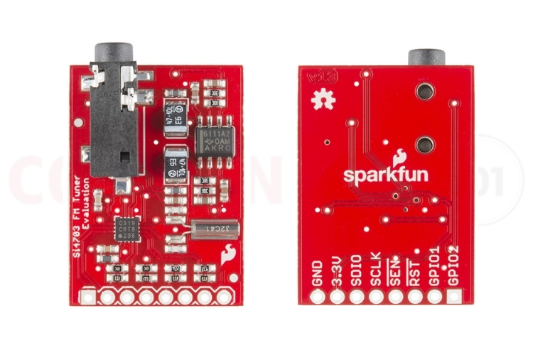
The Si4703 FM tuner module Evaluation Board is a highly integrated and precision FM radio receiver module designed to deliver crystal-clear audio and robust signal reception. Built around the Silicon Labs Si4703 IC. This module supports worldwide FM bands ranging from 76 MHz to 108 MHz, offering excellent sensitivity and selectivity even in low signal environments. With features like automatic seek, tune functions, programmable volume control, and built-in RDS (Radio Data System) support for receiving station names and broadcast text, the Si4703 stands out as a powerful and compact radio solution.
What sets the Si4703 module apart is its comprehensive feature set, including automatic seek and tune functions, programmable volume control, and built-in RDS (Radio Data System) support for displaying station names and broadcast text. Using the I²C interface, the module can be easily integrated with microcontrollers like Arduino, ESP32, Raspberry Pi, and other embedded platforms. Its low power consumption and small form factor make it ideal for applications such as portable FM receivers, alarm clocks, home audio systems, educational radio projects, and DIY electronics. Whether you're building a custom radio receiver, experimenting with wireless communication, or designing an audio-based IoT project, the Si4703 FM tuner Evaluation Board provides a reliable, feature-rich platform for high-quality FM tuning and signal processing.
Understanding the Si4703 FM Tuner Architecture
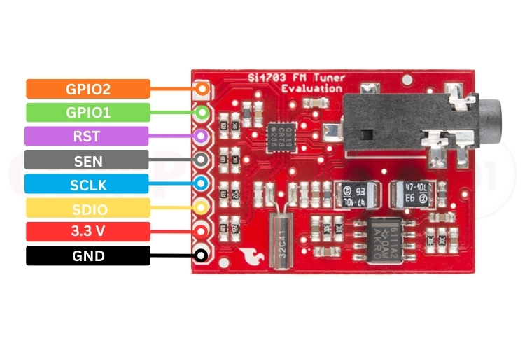
The Si4703 FM Tuner module pin layout is designed for easy integration with microcontrollers using the I²C interface. Each pin serves a specific function required for power, communication, control, and optional status signalling. The following table provides a clear overview of all available pins and their roles for seamless connection and operation. Understanding the Si4703 pinout is essential for successful integration.
|
PIN |
FUNCTION |
DESCRIPTION |
|
GND |
Power |
Connected to the Ground |
|
VCC |
Power |
3.3v Supply |
|
SDIO / SDA |
I²C Data |
I²C data line. Connect to MCU SDA. |
|
SCLK / SCL |
I²C Data |
I²C data line. Connect to MCU SCL. |
|
SEN |
Control / Enable |
Module enable / power-sense pin on some breakouts. Typically tied HIGH (3.3 V) to enable. |
|
RST / RESET |
Input (active LOW) |
Hardware reset. Pull HIGH (3.3 V) for normal operation; drive LOW briefly to reset the Si4703. |
|
GPIO1 |
Digital I/O / Status |
General purpose — often used for interrupts, STC (seek/tune complete), or RDS ready. Can be read by the MCU. |
| GPIO2 |
Digital I/O / Status |
Another general-purpose pin; sometimes used as STC, RDS or other status output. |
Technical Specifications and Features of the Si4703 FM Tuner
The Si4703 datasheet from Silicon Labs provides comprehensive technical specifications.
- FM frequency range: 76–108 MHz
- Digital low-IF FM receiver
- RDS/RBDS support
- I²C (2-wire) control interface
- Auto seek and tune functions
- Programmable volume control
- Integrated oscillator
- Low power consumption
- GPIO1/GPIO2 configurable pins
- 3.3V operating voltage
- Compact breakout module design
| Feature | Specification |
|---|---|
| FM Frequency Range | 76–108 MHz (supports worldwide FM bands including 87.5-108 MHz Europe/US and 76-90 MHz Japan) |
| Receiver Architecture | Digital low-IF FM receiver with integrated DSP |
| RDS/RBDS Support | Full RDS decoder for station ID, program service name, radio text, and time data |
| Control Interface | I²C (Two-Wire Interface) with 7-bit addressing |
| Seek Function | Automatic seek up/down with programmable RSSI threshold and SNR settings |
| Volume Control | 16-level digital volume control (0-15) with software mute capability |
| Clock Source | Integrated 32.768 kHz crystal oscillator (no external components required) |
| Power Consumption | Typical 50mA during reception, <10µA in powerdown mode |
| Operating Voltage | 3.3V (±10% tolerance: 2.7V-3.6V absolute maximum) |
| Sensitivity | -105 dBm typical for 30 dB SNR mono reception |
| Module Dimensions | Compact breakout design (typically 20mm x 20mm for SparkFun variant) |
Si4703 Module Alternatives: Comparative Analysis
When evaluating Si4703 module alternatives, consider these comparable FM tuner ICs, each with distinct advantages for different application requirements:
- Si4702 – Similar FM receiver without RDS support
- Si4705 – Enhanced FM tuner with improved RDS performance
- RDA5807M / RDA5807FP – Low-cost FM tuner ICs with RDS functionality
- TEA5767 – Widely used FM radio module with I²C control
- Si4721 / Si4740 Series – Advanced broadcast radio receivers from Silicon Labs
| Alternative Module | Key Differences | Best Use Case |
|---|---|---|
| Si4702 | Same family as Si4703 but without RDS/RBDS support | Cost-sensitive applications not requiring broadcast data |
| Si4705 | Enhanced FM tuner with improved RDS performance and lower power consumption | Professional audio equipment and battery-powered devices |
| RDA5807M / RDA5807FP | Budget-friendly FM tuner with basic RDS, lower cost but reduced sensitivity | Price-critical consumer electronics and educational projects |
| TEA5767 | Older but widely documented FM radio module with I²C, no RDS support | Simple FM radio projects with extensive community library support |
| Si4721 / Si4740 Series | Advanced broadcast receivers supporting AM/FM/SW with superior DSP | Multi-band radio receivers and advanced automotive systems |
Circuit Design: Si4703 Module Schematic Analysis
Below is the schematic diagram of the module, providing a clear view of its internal circuitry and pin-level connections.
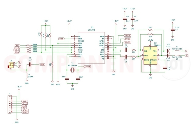
Complete technical details and application circuits are available in the Si4703 datasheet.
Interfacing Si4703 with ESP32: Hardware Connections
The following wiring diagram displays the complete connection layout between the ESP32 and the Si4703 module. The Si4703 ESP32 integration is straightforward thanks to both devices operating at 3.3V logic levels.
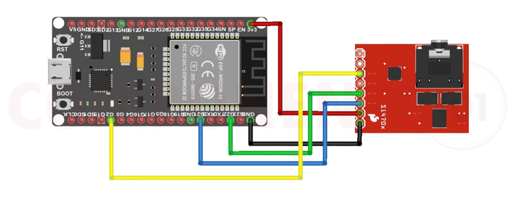
Note: The Si4703 operates strictly at 3.3V logic levels for I²C communication. The Arduino Uno uses 5V I²C pins, which can damage the module if connected directly. Use a 3.3V-compatible board like the ESP32, or add a proper I²C level shifter when using 5V microcontrollers.
| Si4703 Pin | ESP32 Pin | Connection Notes |
|---|---|---|
| VCC | 3.3V | Connect to ESP32's 3.3V output (max current: 50mA typical) |
| GND | GND | Common ground connection essential for stable I²C communication |
| SDIO/SDA | GPIO 21 | I²C data line (ESP32 default SDA). Add 4.7kΩ pull-up to 3.3V if not present on module |
| SCLK/SCL | GPIO 22 | I²C clock line (ESP32 default SCL). Add 4.7kΩ pull-up to 3.3V if not present on module |
| RST/RESET | GPIO 2 | Hardware reset control. Can use any available GPIO pin |
| SEN | 3.3V | Module enable (tie HIGH). Some breakouts handle internally |
Programming Si4703 with Arduino IDE: Complete Code Example
To program the Si4703 module with Arduino IDE, you'll need to install the Si4703 library. To run this code, you must install the VMA11 Arduino Library. The library can be installed from the Arduino Library Manager. The Wire library is also required, but it is included by default in the Arduino IDE.
ESP32 Si4703 Example Code
#include <VMA11.h>
#include <Wire.h>

// I2C pins for ESP32
#define SDA_PIN 21
#define SCL_PIN 22
int resetPin = 2;

VMA11 radio(resetPin, SDA_PIN, SCL_PIN);

int channel;
int volume;
char rdsname[9];
char rdsrt[65];
char previousRadioText[65];
uint8_t lastChar;

void setup() {
  Serial.begin(115200);
  delay(1000);
  Serial.println("\n\n     ESP32 Test Sketch");
  Serial.println("===========================");
  Serial.println("a b     Favourite stations");
  Serial.println("+ -     Volume (max 15)");
  Serial.println("u d     Seek up / down");
  Serial.println("\nSend me a command letter.");

  // Initialize I2C with ESP32 pins
  Wire.begin(SDA_PIN, SCL_PIN);

  radio.powerOn();
  radio.setVolume(1);
  volume = 1;
  radio.setChannel(911);  // 91.1 MHz

  memset(previousRadioText, 0, 65);
  memset(rdsrt, 0, 65);
}

void loop() {
  // Check for new RDS text
  if (radio.readRDSRadioText(rdsrt)) {
    if (strcmp(rdsrt, previousRadioText) != 0) {
      Serial.println(rdsrt);
      strcpy(previousRadioText, rdsrt);
    }
  }

  // Read serial commands
  if (Serial.available()) {
    char ch = Serial.read();
    if (ch == 'u') {
      channel = radio.seekUp();
      displayInfo();
    } else if (ch == 'd') {
      channel = radio.seekDown();
      displayInfo();
    } else if (ch == '+') {
      volume++;
      if (volume >= 16) volume = 15;
      radio.setVolume(volume);
      displayInfo();
    } else if (ch == '-') {
      volume--;
      if (volume < 0) volume = 0;
      radio.setVolume(volume);
      displayInfo();
    } else if (ch == 'a') {
      channel = 911; // Preset station
      radio.setChannel(channel);
      displayInfo();
    } else if (ch == 'b') {
      channel = 935; // Preset station
      radio.setChannel(channel);
      displayInfo();
    }
  }
}

void displayInfo() {
  Serial.print("Channel: "); Serial.print(channel);
  Serial.print(" Volume: "); Serial.println(volume);
}
The example code initializes the Si4703 module and provides interactive control through the Serial Monitor.
Practical Applications of Si4703 FM Tuner
The versatility of the Si4703 FM tuner module makes it suitable for diverse applications across consumer electronics, professional audio, automotive systems, and educational projects:
- FM radio receivers
- Portable audio devices
- Embedded radio systems
- Smart home audio units
- RDS-enabled information displays
- DIY radio and educational projects
- Automotive and infotainment systems
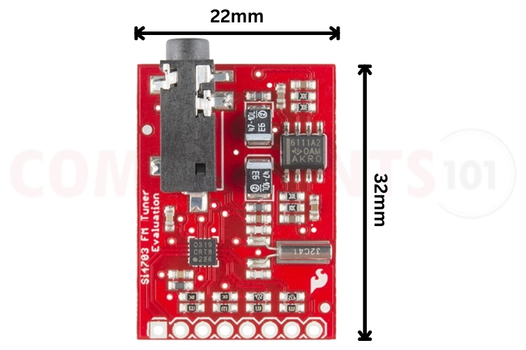
Si4703 Module Dimensions and Mechanical Integration
The SparkFun Si4703 breakout board measures approximately 1" × 1" (25.4mm × 25.4mm) with standard 0.1" (2.54mm) pin spacing, making it compatible with standard breadboards and perfboards.
The outstanding combination of capability, features and integration ease makes the Si4703 FM tuner module an ideal choice for both DIY and commercial FM Radio applications. If you are creating a Si4703 ESP32 radio project, producing a commercial unit, or learning about Radio Frequency (RF) Electronics through experimentation, the Si4703 FM radio module provides solid and dependable FM reception along with professional-grade functionality, including Radio Data System (RDS) decoding and automatic seek.
For complete technical specifications and schematic diagrams for all aspects of design and development, consult the official Si4703 Datasheet.
If you need specific design and development information, such as budget constraints, power consumption or feature requirements, be sure to take a look at the various alternate Si4703 Modules available to you as well.


