MLX90393 Digital Hall Sensor Module

MLX90393 module is a powerful, versatile, ultra-small, universal 3D hall effect sensor module that can be easily fitted into any DIY projects where 3D position detection is required. It provides 44,000uT maximum full-scale resolution with a resolution rate of 0.161uT and requires only 100uA of current.
Compared with the size, it has a very powerful magnetic field sensing ability that can easily detect very small magnetic fields and provides the data via SPI and I2C protocols.
It works as a compass sensor but can also be used as a non-contact controller, linear actuator position sensor, or a flow meter with a magnetic impeller.
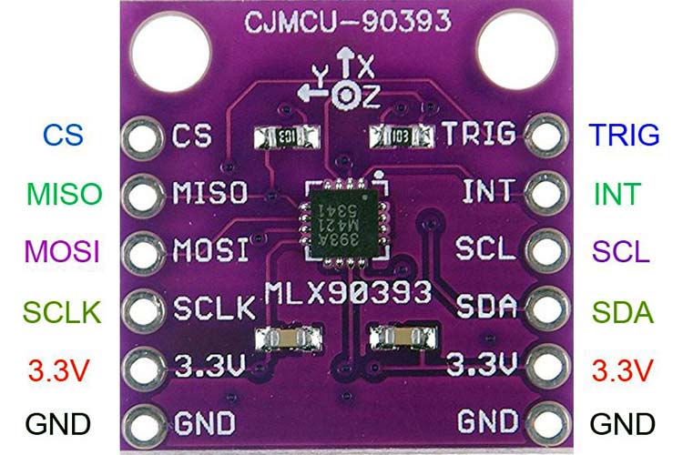
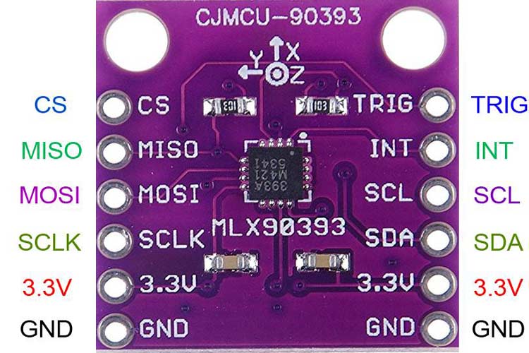
MLX90393 Module Pinout Configuration
|
Pin Number |
Pin Name |
Descriptions |
|
1 |
CS |
SPI Chip select |
|
2 |
MISO |
SPI MISO (Master IN Slave Out) |
|
3 |
MOSI |
SPI MOSI (Master Out Slave In) |
|
4 |
SCLK |
SPI Clock input |
|
5 |
3.3V |
3.3V Input |
|
6 |
GND |
Power supply ground |
|
7 |
GND |
Power supply ground |
|
8 |
3.3V |
3.3V Input |
|
9 |
SDA |
I2C serial data (SDA) |
|
10 |
SCL |
I2C serial clock (SCL) |
|
11 |
INT |
Interrupt Pin |
|
12 |
TRIG |
TRIGGER Pin |
The pinout is shown in the below image-
Features and Specifications
- Operating Voltage: 2.2V-3.6V
- Current Consumption: 100µA (Typ.)
- Operating Temperature: -20°C – 85°C
- Resolution: 0.161µT
- Max Full Scale Resolution: 44,000µT
- I2C Address: 0xC0
- 16-bit AD / high integrated digital, micro power consumption
- I2C & SPI (10MHz) output mode
- XYZT (can be selected first) three-dimensional absolute position output
- Low-cost integrated design
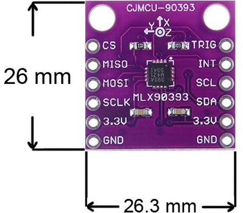
- Size: 26mm x 26.3mm x 5mm (L x W X H)
Note: Complete technical details can be found in the MLX90393 Datasheet linked at the bottom of this page.
MLX90393 Module - Overview
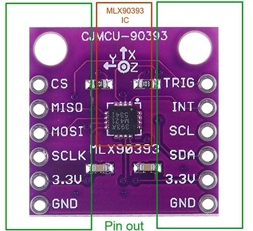
A small size board and excellent for the application of 3D hall effect sensing. The power consumption is too low with 100uA of current from an operating voltage of 2.2V - 3.6V.
The Board uses two communication protocols, I2C, and SPI.
On the bottom side of the board, It uses two solderable jumpers that are useful for selecting the I2C address. Also, the CS pin and Pull UP jumpers are also available on the bottom side of the board.
It uses one Interrupt pin and Trigger pin that can be beneficial for multiple applications.
Interfacing Diagram
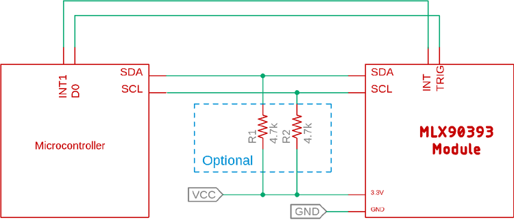
The interfacing is quite easy using an I2C bus. The MLX90393 module can easily be interfaced with any microcontroller having an I2C interface. However, this IC can also be interfaced using SPI protocol.
If the targeted microcontroller does not use I2C pull up resistors, R1 and R2 can be added.
Applications
- Potentiometer
- Remote control, joysticks
- Consumer electronics
- Direction control
2D and 3D Model