MCP2515 CAN Controller Module: Pinout, Specifications and Architecture Guide
The MCP2515 CAN Controller Module is a low-cost CAN interface using the MCP2515 CAN 2.0B controller with a TJA1050 transceiver. It communicates with microcontrollers via SPI and supports speeds up to 1 Mbps, message buffering, filtering, and CAN error handling. The module provides CAN communication capabilities to microcontrollers that do not have an integrated CAN peripheral, including the Arduino UNO / Nano (ATmega328P), Arduino Mega 2560, and Raspberry Pi Pico (RP2040).
This makes it suitable for reliable CAN-based communication on industrial, robotics, and automotive CAN buses. Here we cover the MCP2515 specifications, breakout module and IC pinouts, internal architecture, and comparisons with the integrated MCP25625 SiP and the MCP2518FD CAN FD controller.
MCP2515 CAN Controller: Technical Specifications
| Parameter | Specification |
| CAN Controller IC | Microchip MCP2515 (Standalone CAN Controller with SPI Interface) |
| CAN Protocol Version | CAN V2.0B Active (Supports Standard 11-bit & Extended 29-bit Identifiers) |
| CAN Physical Transceiver | NXP / Philips TJA1050 (High-Speed CAN Transceiver) |
| Maximum CAN Bitrate | Up to 1 Mbps (Standard High-Speed CAN) |
| Host Interface | High-Speed Serial Peripheral Interface (SPI, Modes 0,0 and 1,1) |
| Max. SPI Clock Frequency | Up to 10 MHz |
| Transmit (TX) Buffers | 3 Transmit Buffers with prioritised transmission and abort capabilities |
| Receive (RX) Buffers | 2 Receive Buffers with linked double-buffering (rollover feature) |
| Message Filtering | 6 Acceptance Filters (2 for RXB0, 4 for RXB1) + 2 Acceptance Masks (1 for RXB0, 1 for RXB1) |
| Controller Operating Voltage | 2.7 V to 5.5 V DC (MCP2515 core & logic) |
| Module Operating Voltage | 5.0 V DC (Required for onboard TJA1050 transceiver operation) |
| Operating Current | Active CAN: ~5 mA (typical); Standby/Sleep: ~1 µA (typical) |
| Onboard Crystal Oscillator | 8.000 MHz or 16.000 MHz (Determines SPI clock divider and CAN timing) |
| Bus Termination | Onboard 120 Ω termination resistor selectable via jumper J1 |
| Interrupt Output | Dedicated active-LOW INT pin for transmit, receive, error, and wakeup events |
| Dimensions (Standard Module) | ~40.0 mm × 28.0 mm × 15.0 mm |
| Pin Pitch | 2.54 mm (0.1") standard breadboard pitch |
| Operating Temperature | -40°C to +85°C (Industrial Grade) / -40°C to +125°C (Automotive IC rating) |
The specifications above are drawn from Microchip's official MCP2515 datasheet, which is the authoritative source for timing diagrams, register maps, and electrical characteristics if you're designing the controller into a custom PCB rather than using the breakout module.
MCP2515 Pinout & Pin Configuration
The MCP2515 is available both as a complete breakout module (combining the MCP2515 controller and TJA1050 transceiver) and as a standalone IC for custom PCB designs. Understanding the MCP2515 pinout for both forms is essential whether you're wiring up a breakout board or laying out a custom CAN node.
1. Standard MCP2515 Breakout Module Pinout
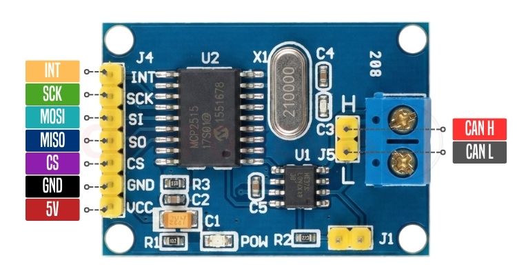
The standard breakout module includes a 7-pin SPI/power header on one side and a 2-pin CAN bus terminal/header on the opposite side.
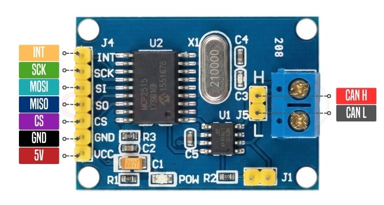
Module Pin Configuration Table
| Pin Label | Pin Type | Function | Description |
| VCC | Power | 5V Power Supply Input | 5.0 V DC power supply (powers both MCP2515 and TJA1050). |
| GND | Power | Ground | Common system ground reference. |
| CS | Input | SPI Chip Select (CSn) | Active-LOW SPI slave select pin. Driven LOW by host MCU to initiate SPI frames. |
| SO | Output | SPI Slave Out (MISO) | Serial data output line from MCP2515 to host microcontroller. |
| SI | Input | SPI Slave In (MOSI) | Serial data input line from host microcontroller to MCP2515. |
| SCK | Input | SPI Serial Clock (SCK) | Serial clock input generated by host MCU (supports up to 10 MHz). |
| INT | Output | Interrupt Output (INTn) | Active-LOW interrupt line. Alerts host MCU of received packets or errors. |
| CAN H | I/O | CAN High Bus Line | High-level differential CAN bus line (connects to CANH network). |
| CAN L | I/O | CAN Low Bus Line | Low-level differential CAN bus line (connects to CANL network). |
| J1 Jumper |
Jumper |
120 Ω Bus Termination | Closed (Jumper ON): Connects the onboard 120 Ω termination resistor between CANH and CANL. Open (Jumper OFF): Disables onboard termination for intermediate bus nodes |
120 Ω Termination Jumper (J1): A high-speed CAN network requires exactly two 120 Ω termination resistors placed at the two extreme physical ends of the bus (total parallel resistance = 60 Ω).
- If this module is located at the end of the CAN network, keep the J1 jumper installed.
- If this module is connected as an intermediate node along an existing terminated bus, remove the J1 jumper to prevent over-terminating the line.
2. Standalone MCP2515 IC Pin Assignment
For custom embedded PCB layouts, the standalone MCP2515 IC is housed in an 18-pin DIP, SOIC, TSSOP, or 20-pin QFN package.
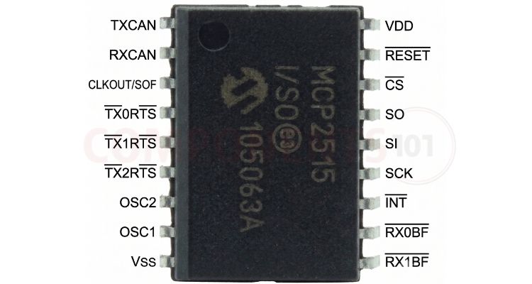
MCP2515 IC Pin Functions
| Pin No | Pin Name | Pin Type | Description |
| 1 | TXCAN | Output | Transmit data output to external CAN transceiver (TXD). |
| 2 | RXCAN | Input | Receive data input from external CAN transceiver (RXD). |
| 3 | CLKOUT/SOF | Output | Programmable clock output or Start-of-Frame (SOF) signal. |
| 4 | TX0RTS | Input | Transmit Buffer 0 Request-to-Send (active-LOW, internal pull-up). |
| 5 | TX1RTS | Input | Transmit Buffer 1 Request-to-Send (active-LOW, internal pull-up). |
| 6 | TX2RTS | Input | Transmit Buffer 2 Request-to-Send (active-LOW, internal pull-up). |
| 7 | RX0BF | Output | Receive Buffer 0 Full interrupt output (active-LOW). |
| 8 | RX1BF | Output | Receive Buffer 1 Full interrupt output (active-LOW). |
| 9 | VSS | Power | Ground reference (0 V). |
| 10 | OSC1 | Input | External crystal oscillator input or external clock source. |
| 11 | OSC2 | Output | External crystal oscillator output. |
| 12 | INT | Output | General interrupt output to host microcontroller (active-LOW). |
| 13 | SCK | Input | SPI clock input from host microcontroller. |
| 14 | SI | Input | SPI data input (MOSI) from host microcontroller. |
| 15 | SO | Output | SPI data output (MISO) to host microcontroller. |
| 16 | CS | Input | SPI chip select input (SCSn, active-LOW). |
| 17 | RESET | Input | Hardware Master Reset input (active-LOW, internal pull-up). |
| 18 | VDD | Power | Positive supply voltage (2.7 V to 5.5 V DC). |
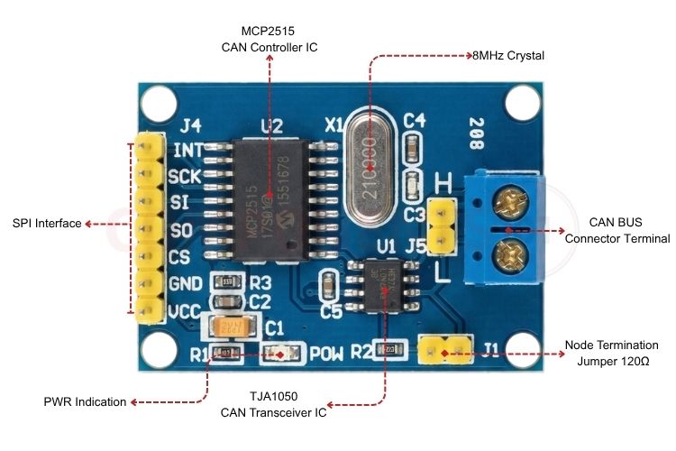
Hardware Layout & Parts Marking
Understanding the component placement on the breakout board assists in system debugging, clock configuration, and level shifting.
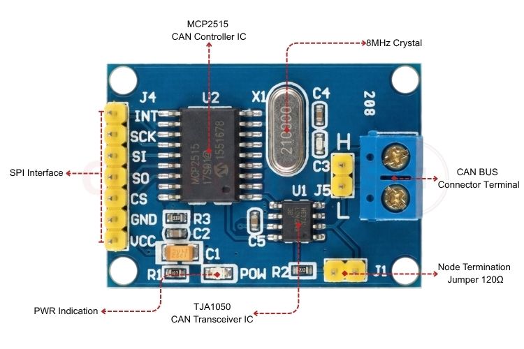
- MCP2515 Standalone CAN Controller: Executes the CAN 2.0B protocol state machine, manages message filtering masks, and arbitrates SPI read/write operations.
- TJA1050 High-Speed CAN Transceiver: Translates the MCP2515's digital TXCAN and RXCAN logic signals into physical differential bus signals (CANH and CANL) with high electromagnetic immunity and low emission.
- 8.000 MHz Crystal Oscillator: Provides the reference clock. When configuring CAN libraries in Arduino or C/C++, specifying the correct crystal frequency is critical; selecting 16 MHz in code for an 8 MHz board results in a 50% baud rate mismatch.
- 120 Ω Termination Resistor & J1 Jumper: Integrated onboard to provide standard transmission-line impedance matching.
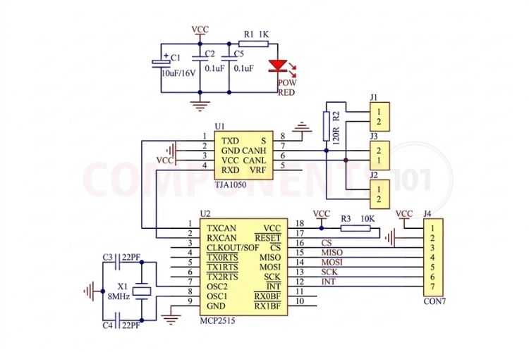
MCP2515 CAN Module Schematic
Understanding the component placement on the breakout board and the MCP2515 CAN module schematic behind it assists in system debugging, clock configuration, and level shifting.
CAN Architecture: How the MCP2515 Is Organised Internally
The internal architecture of the MCP2515 is organised into dedicated functional blocks designed to minimise the host microcontroller's workload:
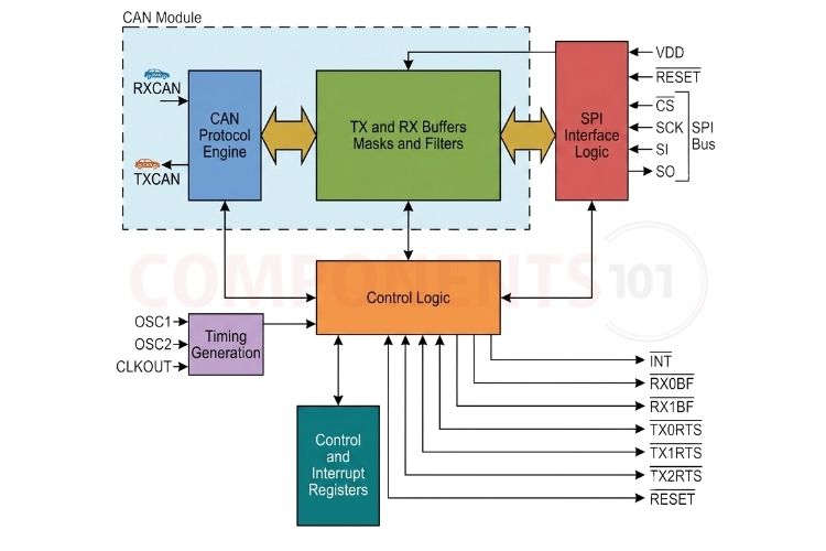
Transmit Buffers (TXB0, TXB1, TXB2)
The MCP2515 includes three independent transmit buffers. Each buffer stores a complete CAN message (Identifier, Data Length Code, and up to 8 data bytes)
| Feature | Description | Example / Purpose |
| Hardware Priority Bits | Higher-priority messages are transmitted before lower-priority messages through CAN bus arbitration | Emergency brake telemetry gets priority over routine sensor updates. |
| Automatic Retransmission | The CAN controller automatically retries transmission when arbitration is lost or an error occurs. | Ensures important messages are retransmitted after a bus error. |
| Abort Feature | Software can cancel a pending transmission before it is sent. | Prevents stale or outdated sensor data from being transmitted. |
Receive Buffers (RXB0, RXB1) & Message Filtering
To prevent packet loss during high-traffic bursts, the MCP2515 implements a two-stage receive FIFO with rollover:
| Feature | Description | Purpose / Benefit |
| RXB0 (High Priority) | Messages are filtered using Acceptance Mask RXM0 and Filters RXF0, RXF1. | Handles higher-priority or critical incoming messages. |
| RXB1 (Standard) | Messages are filtered using Acceptance Mask RXM1 and Filters RXF2, RXF3, RXF4, RXF5. | Handles standard incoming CAN messages. |
| Rollover Feature | If RXB0 is full when a valid matching message arrives, the controller automatically places the message into RXB1. | Prevents valid frames from being dropped when RXB0 is temporarily full. |
| Zero Host Overhead | Unmatched message IDs are rejected directly by the CAN controller hardware. | Reduces MCU processing and ensures the host wakes only for relevant data packets. |
Controller Comparison: MCP2515 vs. MCP25625 vs. MCP2518FD
Microchip provides several tiers of standalone CAN controllers depending on integration requirements and protocol generation.
| Feature | Microchip MCP2515 | Microchip MCP25625 | Microchip MCP2518FD |
| CAN Protocol | CAN 2.0B Active | CAN 2.0B Active | CAN FD & CAN 2.0B |
| Integrated Transceiver | No (Requires external transceiver) | Yes (Integrated Transceiver SiP) | No (Requires external CAN FD transceiver) |
| Max. Bus Data Rate | 1 Mbps | 1 Mbps | Up to 8 Mbps (CAN FD data phase) |
| Max. Payload per Frame | 8 Bytes | 8 Bytes | Up to 64 Bytes |
| Host SPI Interface | Up to 10 MHz | Up to 10 MHz | Up to 40 MHz |
| Message Buffers | 3 TX / 2 RX Buffers | 3 TX / 2 RX Buffers | 31 Configurable FIFO Buffers |
| Acceptance Filters | 6 Filters / 2 Masks | 6 Filters / 2 Masks | 32 Flexible Filter Objects |
| Operating Voltage | 2.7 V to 5.5 V | 4.5 V to 5.5 V (Transceiver rail) | 2.7 V to 5.5 V |
| Package | 18-Pin DIP/SOIC/TSSOP, 20-QFN | 28-Pin SSOP, 28-Pin QFN | 14-Pin SOIC/TSSOP, 14-Pin VDFN |
| PCB Area Savings | Standard | Saves up to 60% board space | Standard |
| Primary Use Case | General MCU CAN breakout modules | Compact automotive/industrial nodes | Next-gen high-throughput CAN FD systems |
Typical Applications
- Automotive Diagnostic Scanners & OBD-II Loggers: Interfacing microcontrollers with standard vehicle OBD-II diagnostic ports.
- Robotics & Motion Control: Linking motor controllers, servo hubs, and central processing units in high-noise environments.
- Industrial Automation: PLC communication, distributed sensor nodes, and fieldbus networking.
- Building Automation: Networked security systems, elevator controls, and environmental telemetry.