KY-040 - Rotary Encoder Module
Description of KY-040 Rotary Encoder
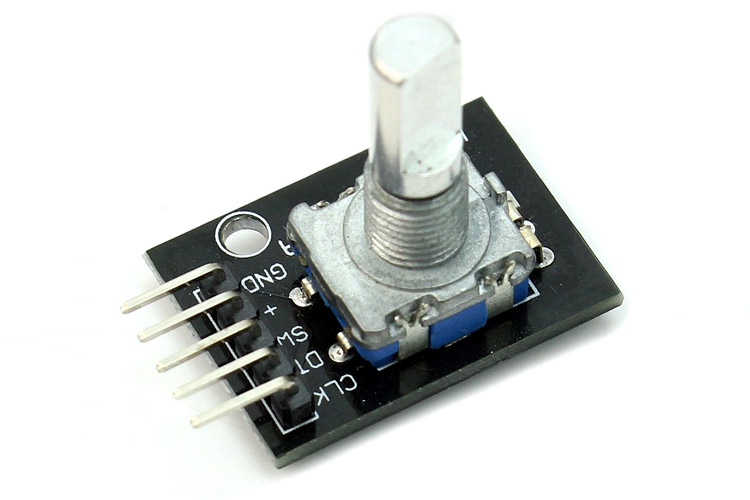
KY-040 rotary encoder is a device that generates an electrical signal based upon how much the
rotary input device (knob) is rotated and the direction it is rotating in. It is a position sensor with a knob and can be used to control stepper or servo motors with precision.
Features and Specifications of KY-040 Rotary Encoder
Below mentioned are some of the features and specifications of the KY-040 Rotary Encoder module:
- Operating Voltage: 5V
- Mechanical angle: 360 Degrees
- Output: 2-bit gray code
- Positions per revolution: 30
Pin Configuration of KY-040 Rotary Encoder
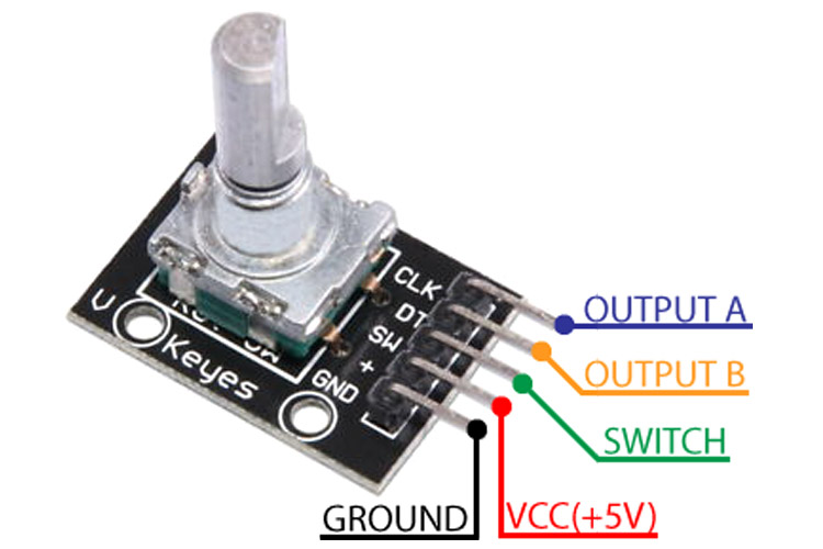
The KY-040 module has 5 output pins. Two of which are for the power of the module whereas, 3 are for the output data of the turns and direction of the knob. The table below describes the pin type and the function of each pin in the Rotary module.
|
Pin Type |
Description |
|
CLK |
Encoder Pin A |
|
DT |
Encoder Pin B |
|
SW |
No push-button switch |
|
VCC(+) |
Voltage input(+5V) |
|
GND |
Ground(Encoder Pin C) |
Alternatives for KY-040 Rotary Encoder
M274, PEL12S-2024S
Note: More technical information can be found in the KY-040 Rotary Encoder Datasheet linked at the bottom of this page.
Connecting KY-040 Rotary Encoder Module with MCU/MPU
Connecting a KY-040 Rotary encoder module to a microcontroller or a microprocessor is quite simple. As mentioned in the section above, there are 5 pins on the encoder module.
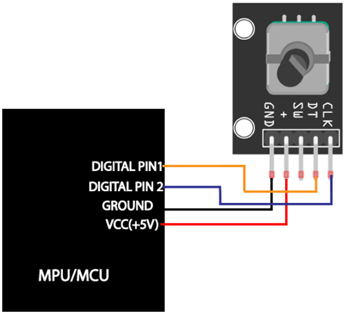
Two pins for the power, +, and ground of the encoder module can be connected to the VCC and the ground terminal of the MCU/MPU, respectively. The CLK and the DT pin both generate a digital output and can be connected to the digital pins of an MCU/MPU.
Working Principle of KY-040 Rotary Encoder
The encoder module generates a digital signal(square pulses) upon the rotation of the knob, let’s see how the encoder module works.
The encoder has a disk with contact pints evenly placed from each other which are connected to the common pin C(Ground). As we start rotating the knob, the disk also moves and makes contact with the output pins A and B one by one, hence generating two square waves simultaneously. Simply by counting the number of square waves generated, the rotated position can be determined. A simple program can be written to monitor the number of waves generated and output can be extracted.
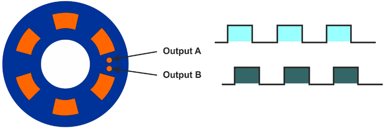
To know the direction of rotation, determining how the switch changes its position is essential.
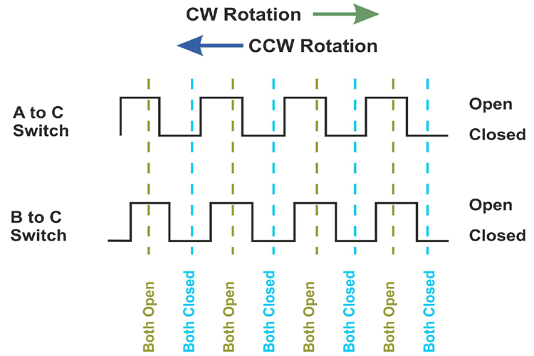
If output A changed states first, the switch is rotating in a clockwise direction, whereas if output B changes its state first, we know that the switch is rotating in a counter-clockwise direction.
Applications for KY-040 Rotary Encoder
Here are some of the applications of the KY-040 rotary encoder module:
- Robotic arm controller
- Servo and Stepper motor control
- Precise motor movement
2D Model of KY-040 Rotary Encoder
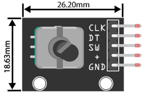
This section provides the 2D model of the rotary module along with its dimensions. This information can be used to design custom footprints of the module, which can further be used for PCB and CAD model designing.


