Rotary Encoder Module
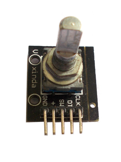
ROTORY ENCODER is a device used for knowing the axial movement and its direction. Although they are available in various types; here we are going to discuss about simple contact type encoder module. Here we are going to use M274 ROTARY ENCODER MODULE.
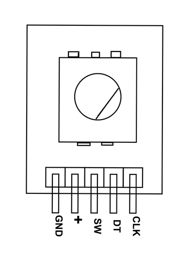
ROTARY ENCODER MODULE Pin Configuration
ROTARY ENCODER module is five pin device as shown in the M274 pinout. In them four pins are compulsory for using the module.
|
Pin Name |
Description |
|
GND |
Connected to GROUND |
|
+ |
Connected to +5V |
|
SW |
Output of internal button |
|
DT |
Contact A output or DATA |
|
CLK |
Contact B output or CLOCK |
In the above pins Contact A or DT and Contact B or CLK are used to measure the axis movement and direction.
ROTARY ENCODER MODULE Features and Specifications
- 360º free rotation.
- 20 steps or cycles per revolution
- Incremental type encoder
- Can work on low voltages
- Maximum operating temperature: 0°C to + 80°C
- Easy interface
- Long life.
Where M274 ROTARY ENCODER MODULES are Used?
Here are few applications where M274 is chosen over other encoder modules
Case1: M274 is used when the cost of installment is considered. M274 is one of cheapest and robust encoders on the market. It is easily available to invest and replace.
Case2: M274 is easy to work with considering the complex modules out there. We only need to consider two outputs to work with this module.
Case3: With this encoder we can measure the axial movement and also the direction of change.
Also the module does not need any additional components to install in a system
How to Use M274 ROTARY ENCODER MODULES
For understanding the working of M274 rotary encoder, consider the simple circuit configuration shown below.
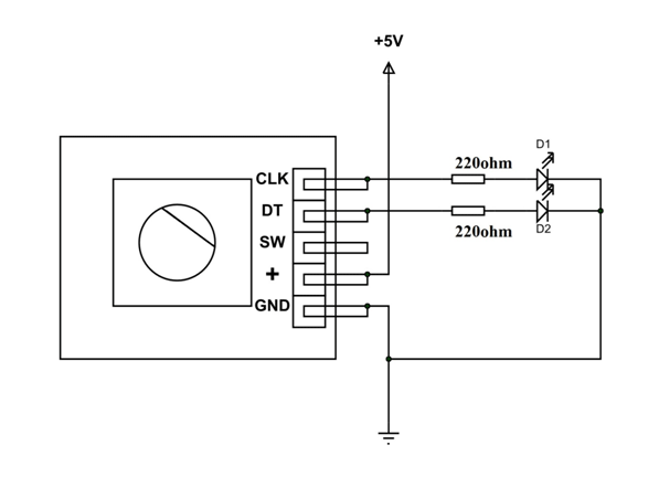
Here we have connected two outputs to two LEDs to check the state of the module. The button is of no use here so it left alone. The module is powered by +5V power source. Now for understanding the output of encoder let us consider internal stricture of encoder.
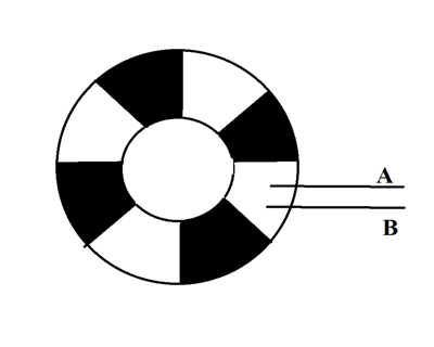
Here A and B are outputs and these contacts are left sliding internally on a rotating disk. This disk has divided in to conductive (dark segment) and nonconductive segments (white segments) as shown in figure. The conductive contacts or dark segments are jointly connected to +5V. So when the points come in contact with dark segments they are simply coming in contact with +5V.
Now when the disk rotates clock wise, the point A comes in contact with conductive segment (dark part) first and provides an output +5V. After that point B comes in contact with conductive segment and provides +5V. So in the circuit D1 LED turns ON first following D2 LED. Hence when the axis of encoder is rotated clock wise point A provides +5V first and then B provides +5V.
If the axis keeps rotating the point A leaves the conductive segment (dark part) and moves on to nonconductive part (white part). So the output A goes LOW. Next the point B leaves conductive part making output B LOW. With that D1 turns OFF first next D2 turns OFF.
If the axis keeps rotating the cycle repeats and output A goes high following output B. So we will have a pulse output every time the points move from one segment to other.
As these pulses state the change of axis, we can take them as a measure for axial movement. If this logic signal is given to controller, the controller can measure the clockwise axial movement.
Similarly if the disk moves anti-clockwise, point B comes in contact with conductive segment first providing +5V at output B. With disk keep moving point A comes in contact with dark segment. With that output A gives +5V. So in the circuit D2 LED turns ON first after that D1 LED turns ON. Turning OFF also follows the same pattern to complete a cycle. For every cycle there will be voltage pulse at the output.
As before these voltage signals represent the axial movement. We can take them as a measure for axial movement. If this logic signal is given to controller, the controller can measure the anticlockwise axial movement.
This way we can find the axial movement and the direction of rotation through rotary encoder.
Applications
- Security systems.
- Motors
- Robotic arms
- Vending machines.
- Industrial machines.
- Engineering systems.
- Measuring instruments.
- Hobby projects.
- Systems where systematic change INPUT device is needed like CROs, signal generator, etc.
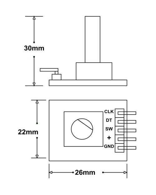
2D Model
All measurements are given in millimeters.