STM32F030F4 Arm-based 32-bit Microcontroller
The STM32F030F4 microcontroller incorporates the high-performance Arm Cortex-M0 32-bit RISC core operating at a 48 MHz frequency, high-speed embedded memories (up to 256 Kbytes of Flash memory and up to 32 Kbytes of SRAM), and enhanced peripherals and I/Os. All devices offer standard communication interfaces (up to two I2Cs, up to two SPIs, and up to six USARTs), one 12-bit ADC, seven general-purpose 16-bit timers, and an advanced-control PWM timer.
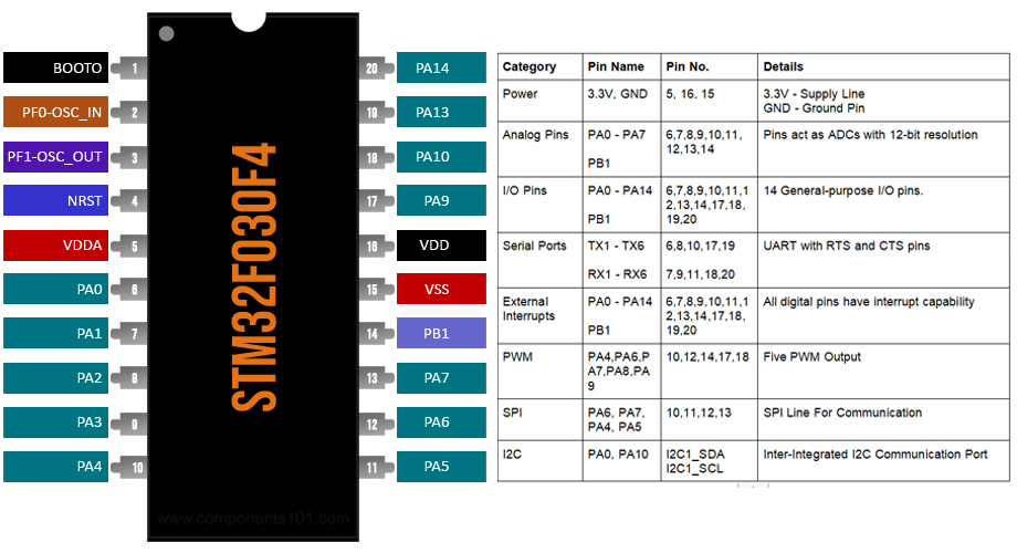
STM32F030F4 Pinout Configuration
|
Category |
Pin Name |
Pin No. |
Details |
|
Power |
3.3V, GND |
5, 16, 15 |
3.3V - Supply Line |
|
Analog Pins |
PA0 - PA7
PB1 |
6,7,8,9,10,11, 12,13,14 |
Pins act as ADCs with 12-bit resolution |
|
I/O Pins |
PA0 - PA14
PB1 |
6,7,8,9,10,11,12,13,14,17,18,19,20 |
14 General-purpose I/O pins. |
|
Serial Ports |
TX1 - TX6
RX1 - RX6 |
6,8,10,17,19
7,9,11,18,20 |
UART with RTS and CTS pins |
|
External Interrupts |
PA0 - PA14
PB1 |
6,7,8,9,10,11,12,13,14,17,18,19,20 |
All digital pins have interrupt capability |
|
PWM |
PA4,PA6,PA7,PA8,PA9 |
10,12,14,17,18 |
Five PWM Output |
|
SPI |
PA6, PA7, PA4, PA5 |
10,11,12,13 |
SPI Line For Communication |
|
I2C |
PA0, PA10
|
I2C1_SDA I2C1_SCL |
Inter-Integrated I2C Communication Port |
Features and Specifications
- Max Operating Voltage 2.4 -3.6V
- 16Kb Flash with 4Kb RAM
- Arm 32-bit Cortex-M0 CPU, frequency up to 48 MHz
- Internal 8 MHz RC with x6 PLL option
- Internal 40 kHz RC oscillator
- 5-channel DMA controller
- One 16-bit advanced-control timer for six-channel PWM output
- Up to seven 16-bit timers, with up to four IC/OC
- Up to two I2C interfaces
- Up to six USARTs supporting master
- Serial wire debug
- CRC calculation unit
Note: Complete technical information can be found in the STM32F030F4 Datasheet, given at the bottom of this page.
Other STM32 ICS
STM32F030C6, STM32F030C8, STM32F030CC, STM32F103C8T6, STM32 Nucleo
How to Use the STM32F030F4 IC
As this is a Microcontroller it needs to be programmed in order to work with it and there are two ways you can program this IC, the first way is to use an STLink USB Dongle which uses the single-wire debug interface to communicate with the IC. This allows it to be programmed using advanced software like Keil/CubeMX. It also allows memory access using the STLink software. Another way is to use an external USB to Serial Converter to program the device but for that, you need an IC that has a pre-programmed bootloader or you need to program the IC with a Specific bootloader.
Applications
- Rapid prototyping
- CRC calculations
- Robotics
- Consumer products
- Drone controllers
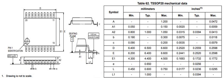
2D Model and Dimensions
If you are looking to include this IC for your next PCB project this 2D model of the device will come in handy.


