ATtiny45 Microcontroller

ATTINY45 is high performance, low power controller from ATMEL. It is an 8 bit controller based on Advanced RISC architecture. It is one of members of ATTINYXX series, popular because of its small size and features.
Pin Configuration
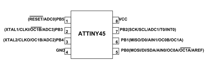
ATTINY45 is an 8 pin iC as shown in the ATtiny45 pin diagram above. All I/O pins of the chip here have more than one function. We will describe functions of each pin in below table.
|
Pin No. |
Pin name |
Description |
Secondary Function |
|
1 |
PB5 (RESET/ADC0) |
Pin5 of PORTB |
|
|
2 |
PB3 (XTAL1/CLKI/OC1B/ADC3) |
Pin3 of PORTB |
|
|
3 |
PB4 (XTAL2/CLK0/OC1B/ADC2) |
Pin4 of PORTB |
|
|
4 |
GND |
Connected to ground |
|
|
5 |
PB0(MOSI/DI/SDA/AIN0/OC0A/OC1A/AREF) |
Pin0 of PORTB |
|
|
6 |
PB1(MISO/D0/AIN1/OC0B/OC1A) |
Pin1 of PORTB |
|
|
7 |
PB2(SCK/SCL/ADC1/T0/INT0) |
[Serial Peripheral Interface (SPI) for programming]
|
|
|
8 |
VCC |
Connected to positive voltage |
ATTINY45 Microcontroller Features
|
ATTINY45 –Simplified Features |
|
|
CPU |
8-bit AVR |
|
Number of Pins |
8 |
|
Operating Voltage (V) |
+1.8 V TO +5.5V (ATTINY45V) +2.7 VTO+5.5V (ATTINY45)(+5.5V being absolute maximum) |
|
Number of I/O pins |
6 |
|
Communication Interface |
Master/Slave SPI Serial Interface(5,6,7 PINS) [Can be used for programming this controller] Two-wire Serial Interface(5,7 PINS)[Can be used to connect peripheral devices like sensors and LCDs] Universal Serial Interface (5,6 PINS) [Can be used for communicating with other controllers] |
|
JTAG Interface |
Not available |
|
UART Interface |
Not available |
|
ADC Module |
4channels, 10-bit resolution ADC |
|
Timer Module |
Two8-bit counter |
|
Analog Comparators |
1 |
|
DAC Module |
Nil |
|
PWM outputs |
4 |
|
External Oscillator |
0-10MHz for ATTINY45V 0-20MHz for ATTINY45 |
|
Internal Oscillator |
0-8MHz Calibrated Internal Oscillator |
|
Program Memory Type |
Flash |
|
Program Memory or Flash memory |
4Kbytes[10000 write/erase cycles] |
|
CPU Speed |
1 MIPS@1MHz |
|
RAM |
256Bytes |
|
EEPROM |
256Bytes |
|
Watchdog Timer |
Programmable Watchdog Timer with Separate On-chipOscillator |
|
Program Lock |
Yes |
|
Power Save Modes |
Three Modes[Idle, ADC Noise Reduction, Power-down] |
|
Operating Temperature |
-55°C to +125°C(+125 being absolute maximum, -55 being absolute minimum) |
Note: Complete technical information ca be found in the ATTINY45 Datasheet linked at the bottom of this page.
ATTINY45 Alternatives
ATTINY25, ATTINY85, ATTINY2313
Where to Use ATtiny45 Microcontroller?
- ATTINY45is an 8 pin AVR controller and so application program can be developed in AVR IDE which has many references.
- Although we have many controllers, ATTINY is popular because it is one of cheapest.
- Also ATTINY provides many features in lesser pins.
- With program memoryof 4Kbytes the controller can be used in many applications.
- With variousPOWER SAVING modes it can work on MOBILE EMBEDDED SYSTEMS.
- With its small and compact size it can be put in many small boards.
- With Watchdog timer and other features the use on ATTINY45 is further promoted.
How to Use ATTINY45
Like any other controller ATTINY45 works based on application program, i.e. execute the application program saved in its memory.
The procedure to program an ATTINY45 microcontroller is described below:
- First list the functions to be executed by controller.
- Write the functions in programming language in IDE programs.
You can download the IDE program for free in company websites. IDE program for AVR controllers is ‘ATMEL STUDIO’. Link for ATMELSTUDIO is given below.
(Usually Atmel Studio 6.0 for Windows7 [ http://atmel-studio.software.informer.com/6.0/ ],
Atmel Studio 7 for Windows10 [ https://www.microchip.com/avr-support/atmel-studio-7 ])
- After writing the program compile it to eliminate errors.
- Make the IDE generate HEX file for the written program after compiling.
- This HEX file contains the machine code which should be saved in controller flash memory.
- Choose the programming device (usually SPI programmer made for AVR controllers) which establishes communication between PC and ATTINY45.Programming ATTINY45can also be done by using ARDUINO boards.
- Run the programmer software and choose the appropriate hex file.
- Burn the HEX file of written program in ATTINY45 flash memory using this program.
- Disconnect the programmer, connect the appropriate peripherals for the controller and get the system started.
Applications
- Used in development boards.
- Hobby projects
- Drivers
- Industrial control systems.
- SMPS and Power Regulation systems.
- Analog signal measuring and manipulations.
- Embedded systems like coffee machine, vending machine.
- Display units.
- Peripheral Interface system.
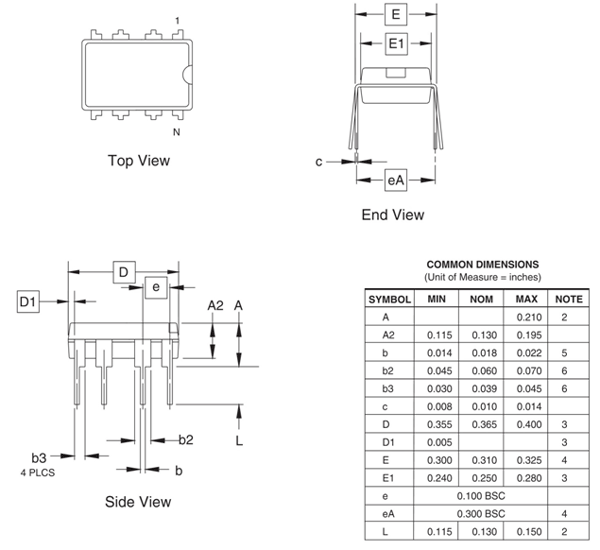
2D Model
All measurements are in millimeters.