ATtiny85 Microcontroller
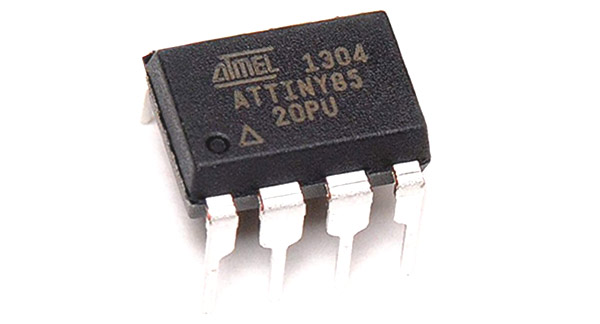
ATtiny85 is a high performance, low power 8-bit microcontroller based on Advanced RISC Architecture. It has 8 Kbytes of In-System Programmable Flash and is popular because of its compact size and its features.
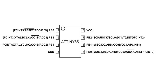
Attiny85 Pin Configuration
It is an 8 pin IC as shown in Atiny85 pin diagram shown above. Most I/O pins of the chip have more than one function and description for each pin is given below.
|
Pin no. |
Pin Name |
Description |
Secondary Function |
|
1 |
PB5 (PCINT5/ADC0/dW) |
Pin5 of PORTB |
PCINT5 : Pin Change Interrupt 0, Source5 RESET : Reset Pin ADC0 : ADC Input Channel 0 dW : debug WIRE I/O |
|
2 |
PB3 (PCINT3/XTAL1/CLKI/ADC3) |
Pin3 of PORTB
|
PCINT3 : Pin Change Interrupt 0, Source3 XTAL1 : Crystal Oscillator Pin1 CLKI : External Clock Input OC1B : Complementary Timer/Counter1 Compare Match B Output ADC3 : ADC Input Channel 3 |
|
3 |
PB4 (PCINT4/XTAL2/CLKO/OC1B/ADC2) |
Pin4 of PORTB |
PCINT4 : Pin Change Interrupt 0, Source 4 XTAL2 : Crystal Oscillator Pin 2 CLKO : System Clock Output OC1B: Timer/Counter1 Compare Match B Output ADC2 : ADC Input Channel 2 |
|
4 |
GND |
|
Connected to Ground |
|
5 |
PB0(MOSI/DI/SDA/AIN0/OC0A/AREF/ PCINT0) |
Pin0 of PORTB |
MOSI : SPI Master Data Output / Slave Data Input DI : USI Data Input (Three Wire Mode) SDA : USI Data Input (Two Wire Mode) AIN0 : Analog Comparator, Positive Input OC0A : Timer/Counter0 Compare Match A output : Complementary Timer/Counter1 Compare Match A Output AREF : External Analog Reference PCINT0 : Pin Change Interrupt 0, Source 0 |
|
6 |
PB1(MISO/D0/AIN1/OC0B/OC1A/ PCINT1) |
Pin1 of PORTB |
MISO : SPI Master Data Input / Slave Data Output DO : USI Data Output (Three Wire Mode) AIN1 : Analog Comparator, Negative Input OC0B : Timer/Counter0 Compare Match B Output OC1A: Timer/Counter1 Compare Match A Output PCINT1 : Pin Change Interrupt 0, Source 1 |
|
7 |
PB2(SCK/USCK/SCL/ADC1/T0/INT0/ PCINT2) |
Pin2 of PORTB |
SCK : Serial Clock Input USCK : USI Clock (Three Wire Mode) SCL : USI Clock (Two Wire Mode) ADC1 : ADC Input Channel 1 T0 : Timer/Counter0 Clock Source INT0 : External Interrupt 0 Input PCINT2 : Pin Change Interrupt 0, Source 2 |
|
8 |
VCC |
|
Connected to positive voltage |
Features and Electrical Characteristics
|
CPU |
8 bit |
|
Number of Pins |
8 |
|
Number of Programmable I/O pins |
6 |
|
Operating Voltage |
+1.8 V to +5.5V (ATTINY85V) +2.7 V to +5.5V (ATTINY85)(+6.0V being absolute maximum supply voltage) |
|
Maximum DC Current per I/O Pin |
40 mA |
|
Maximum DC Current through VCC and GND Pins |
200 mA |
|
Operating Temperature |
-55ºC to +125ºC |
|
Communication Interface |
Master/Slave SPI Serial Interface(5,6,7 PINS) [Can be used for programming this controller] I2C or Two-wire Serial Interface(5,7 PINS)[Can be used to connect peripheral devices and sensors] Universal Serial Interface (5,6,7 PINS) [Can be used for communicating with other controllers] |
|
UART Interface |
Not available |
|
ADC Feature |
4channels, 10-bit resolution ADC |
|
Analog Comparators |
1 |
|
Timer Module |
Two 8-bit counter |
|
PWM outputs |
4 |
|
External Oscillator |
0-10MHz for ATTINY85V 0-20MHz for ATTINY85 |
|
Internal Oscillator |
0-8MHz Calibrated Internal R-C Oscillator |
|
CPU Speed |
1 MIPS@1MHz |
|
Program Memory or Flash memory size |
8Kbytes[10000 write/erase cycles] |
|
RAM size |
512Bytes on Internal SRAM |
|
EEPROM size |
512Bytes of In-System Programmable EEPROM |
|
Program Lock |
Available |
|
Watchdog Timer |
Available |
|
Power Save Modes |
Three Modes[Idle, ADC Noise Reduction, Power-down] |
Note: Complete technical details can be found in the ATtiny85 Microcontroller Datasheet linked at at the bottom of this page.
ATTINY85 Alternatives
ATTINY25, ATTINY45, ATTINY25V, ATTINY45V, ATTINY85V
Brief About ATTINY85 Microcontroller
- ATTINY85 is cheap and easily available for experimenting
- ATTINY85 has many reference data available making it easy to work with.
- Also ATTINY85 provides many features in lesser pins.
- With program memory of 8Kbytes the controller has satisfying memory for many applications.
- With various POWER SAVE modes it can work on battery operated applications.
- With its small and compact size it can be put in many small boards.
- With watchdog timer and other features the use on ATTINY85 is further promoted.
How to use ATTINY85 Microcontroller
ATTINY85 works like any other microcontroller. If stated in one sentence, all that microcontrollers do is execute the application program saved in its memory. So in the case of controllers all there to do is write application program. Without programming controller simply stays idle.
Step by step procedure for programming ATTINY85 is explained below:
- First list the tasks to be done by the designing application.
- Write down the functions to be executed by controller to complete required tasks.
- Develop the program code for the functions in IDE software.
- After writing the program compile it to eliminate errors.
- Make the IDE generate HEX file for the written program after compiling.
- This HEX file contains the machine code which should be saved in microcontroller flash memory.
- Choose the programming device (usually SPI programmer made for AVR microcontrollers) which establishes communication between PC and ATTINY85. You can also program the microcontroller using UART Interface. Programming ATTINY85 can also be done by using ARDUINO boards.
- Run the programmer software and choose the appropriate hex file.
- Burn the HEX file of written program in ATTINY85 flash memory using this program.
- After disconnecting the programmer connect the appropriate peripherals for the controller and get the system started.
Once powered, the ATTINY85 executes the machine code saved in its memory to create the programmed response.
Applications
The applications of ATTINY85 are many and a few are stated below
- Used in development boards.
- Hobby projects
- Drivers
- Industrial control systems.
- SMPS and Power Regulation systems.
- Analog signal measuring and manipulations.
- Embedded systems like coffee machine, vending machine.
- Display units.
- Peripheral Interface system.
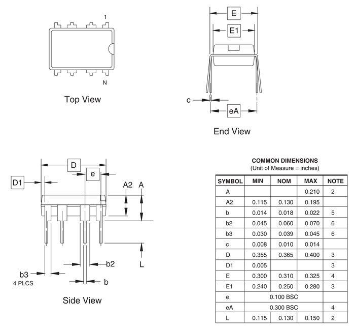
2D Model and Dimensions