H20R1203 (IHW20N120R3) 1200V 20A IGBT Pinout, Specifications, Marking Code & Datasheet
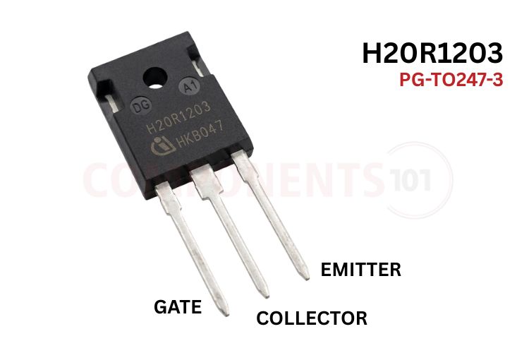
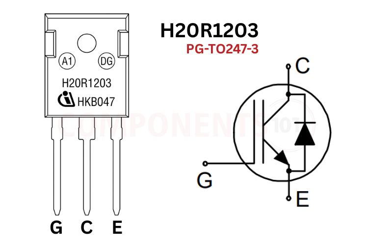
H20R1203 Pinout Configuration
The H20R1203 pinout follows the standard TO-247 order.
| Pin Number | Pin Name | Description |
| 1 | Gate (G) | Controls the IGBT turn-on and turn-off state. Driven with +15V relative to the emitter for full saturation. |
| 2 | Collector (C) | High-voltage collector terminal connected to the resonant LC tank circuit. Internally connected to the heatsink tab. |
| 3 | Emitter (E) | Power return terminal connected to circuit ground via a low-resistance current-sense shunt. |
| Tab | Collector (C) | Metal mounting tab electrically bonded to Pin 2 Collector for direct thermal mounting to heatsinks. |
H20R1203 Package, Marking Code and Dimensions
The H20R1203 is housed in a standard through-hole TO-247 package with laser-etched markings on its epoxy resin body:
| Marking Field | Laser Stamped Code | Description & Significance |
| Manufacturer | Infineon Logo | Official manufacturer branding (Infineon Technologies). |
| Model Code |
H20R1203 IHW20N120R3 |
Shorthand OEM designation: H = High-Frequency Induction Series, 20 = 20A Rated Current, R = Reverse-Conducting Diode, 120 = 1200V Breakdown, 3 = Generation 3 TrenchStop. |
| Traceability | Lot / Date Code | Alphanumeric batch code indicating the manufacturing year, work week, and fabrication line. |
*Note: In the appliance repair trade and retail markets, this component is universally requested and catalogued as H20R1203, while official engineering documentation and CAD libraries use the formal part number IHW20N120R3.
H20R1203 Key Features & Specifications
- Transistor Type: Reverse-Conducting N-Channel IGBT with Integrated Monolithic Diode
- Semiconductor Technology: Infineon TrenchStop Technology (Generation 3)
- Collector-Emitter Breakdown Voltage (VCES): 1200V
- Continuous Collector Current (IC): 40A at TC = 25°C, 20A at TC = 100°C
- Pulsed Collector Current (ICpuls): 60A
- Collector-Emitter Saturation Voltage (VCE(sat)): 1.48V typ (1.70V max) at VGE = 15V, IC = 20A
- Diode Forward Voltage (VF): 1.35V typ (1.60V max) at IF = 20A, VGE = 0V
- Gate-Emitter Threshold Voltage (VGE(th)): 5.1V min, 5.8V typ, 6.4V max (at IC = 0.5mA)
- Maximum Gate-Emitter Voltage (VGE): ±20V continuous (±25V transient for tp ≤ 500 ns)
- Maximum Power Dissipation (Ptot): 310W at TC = 25°C (155W at TC = 100°C)
- Operating Junction Temperature (Tj): -40°C to +175°C
- Turn-Off Fall Time (tf): 28 ns typical (Ultra-fast resonant turn-off)
- Package Type: PG-TO247-3 Through-Hole Power Package
*Note: Complete Technical Details can be found in the H20R1203 datasheet given at the end of this page.
H20R1203 Equivalent and Alternative IGBTs
| Equivalent Part | Technology | Key Ratings | Description & Application Suitability |
| H15R1203 (IHW15N120R3) | RC-IGBT | 1200V, 15A, TO-247 | Lower-current direct sibling from Infineon for budget 1400W to 1800W induction plates. |
| H25R1203 (IHW25N120R3) | RC-IGBT | 1200V, 25A, TO-247 | Higher-power direct upgrade from Infineon for commercial 2200W to 2500W induction cookers. |
| FGA25N120ANTD | NPT-IGBT | 1200V, 25A, TO-3P | onsemi / Fairchild resonant IGBT with built-in diode; a common alternative in induction repair. |
| FGA15N120ANTD | NPT-IGBT | 1200V, 15A, TO-3P | 15A predecessor from Fairchild for standard induction cooktop resonant stages. |
| IKW20N120H3 (K20H1203) | Hard-Switch IGBT | 1200V, 20A, TO-247 | High-speed 3-industrial IGBT with separate co-packaged diodes for hard-switching inverters. |
Brief Description of H20R1203
The H20R1203 represents a specialized branch of discrete power semiconductors designed specifically for single-switch resonant topologies. In standard power switching applications, an IGBT combines the high input impedance and simple voltage-controlled gate drive of a MOSFET with the high current density and low conduction drop of a bipolar junction transistor.
However, induction cooktops impose a unique set of harsh operating requirements that standard power MOSFETs and standard IGBTs struggle to withstand:
1. High Voltage Stresses: Operating directly from rectified 230V AC mains, a resonant tank circuit creates sinusoidal voltage swings that peak at 900V to 1150V during switch turn-off. A 1200V breakdown rating provides the required safety margin to prevent avalanche breakdown.
2. Reverse Commutation Current: In a quasi-resonant tank, the reactive energy stored in the induction heating coil alternates direction every cycle. The H20R1203 integrates a monolithic body diode on the same silicon die, eliminating external freewheeling diode packaging costs, reducing stray parasitic inductance, and enabling seamless Zero-Voltage Switching (ZVS).
3. Thermal Ruggedness: With an extended maximum junction temperature of +175°C, the H20R1203 provides extraordinary resilience against overheating during pan-removal events or prolonged high-heat boiling cycles.
H20R1203 Datasheet
The complete original manufacturer technical specifications, switching loss waveforms, and thermal impedance graphs are available in the official PDF H20R1203 datasheet.
How the H20R1203 Works in an Induction Cooker Circuit
The H20R1203 is deployed in a single-ended quasi-resonant inverter topology. In this circuit, the device acts as the main high-frequency power switch controlling energy transfer to the primary induction coil.
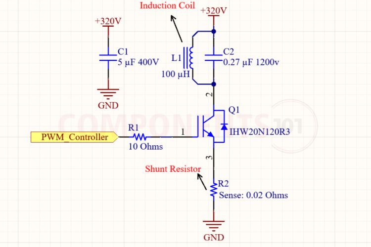
Circuit Operation & Design Considerations
1. Rectification and DC Bus Filtering:
The 230V AC mains input is rectified by a high-power single-phase bridge rectifier (such as a GBU808 or D25XB60). Unlike standard DC power supplies that use thousands of microfarads of electrolytic capacitance, an induction cooker utilises a small high-voltage polypropylene film capacitor (typically 5 μF / 400V MKP). This provides low high-frequency impedance while leaving the DC bus pulsating at 100 Hz, enabling natural power-factor correction.
2. The Quasi-Resonant LC Tank:
The induction work coil (Lr ≈ 100 μH, formed by wound litz wire) and a specialized resonant capacitor (Cr ≈ 0.27 μF to 0.33 μF rated at 1200V MKP) are connected in parallel. When the H20R1203 turns ON, current ramps linearly through the coil, storing magnetic energy. When the H20R1203 turns OFF, the coil current cannot stop instantaneously and transfers into Cr, creating a resonant half-sine voltage pulse across the collector that can reach 1000V.
3. Zero-Voltage Switching (ZVS) & Diode Commutation:
As the resonant oscillation completes its half-cycle, the voltage across Cr collapses back toward zero and swings slightly negative. At this precise instant, the monolithic anti-parallel diode inside the H20R1203 turns on, clamping the collector voltage to -1.35 V and returning resonant energy to the bus. The microcontroller synchronisation circuit detects this zero-voltage crossing and triggers the next gate pulse, achieving Zero-Voltage Switching (ZVS) with virtually zero capacitive turn-on losses.
4. Gate Drive Requirements:
To achieve the rated VCE(sat) of 1.48V, the gate must be driven with a solid +15V to +18V supply (typically derived from an auxiliary VIPer12A or SMPS rail). A dedicated gate driver circuit using a complementary push-pull pair (such as SS8050 / SS8550) or a comparator (LM339 / TA75393) delivers peak charging currents through a low-value gate resistor (RG ≈ 10 Ω to 22 Ω). An 18V Zener diode placed directly between the gate and emitter protects the thin oxide layer from voltage spikes.
5. Current Sensing and Protection:
A low-value shunt resistor (0.01 Ω to 0.05 Ω, 5W) is inserted between Pin 3 (Emitter) and circuit ground. The voltage drop across this shunt is fed to the microcontroller comparator to detect overcurrent conditions (such as ferromagnetic pan mismatch or short circuits) and shut down gate drive pulses within microseconds.
Applications of the H20R1203
- Domestic Induction Cooktops: The primary resonant switching power device in 1800W to 2100W domestic induction cooktops from brands including Philips, Prestige, Bajaj, Midea, Pigeon, and Hawkins.
- Commercial Induction Heating Ranges: Paralleled or single-stage resonant modules for commercial catering equipment and soup warmers.
- Inverterized Microwave Ovens: Variable-power magnetron resonant inverter drivers operating at 20 kHz to 45 kHz.
- High-Frequency Induction Heaters: DIY and workshop induction annealing furnaces, bolt heaters, and small metal smelting crucibles.
- Resonant SMPS & Soft-Switching Converters: High-efficiency DC-DC resonant converters requiring compact, high-voltage switching with built-in reverse conduction.
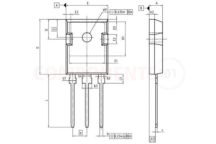
2D Model and Component Dimensions
For engineers creating custom PCB footprints or technicians replacing damaged components, the physical dimensions for the standard PG-TO247-3 package are detailed below:
| Mechanical Parameter | Minimum (mm) | Typical (mm) | Maximum (mm) |
| Total Body Length (D) | 20.80 | 20.95 | 21.10 |
| Total Body Width (E) | 15.75 | 15.90 | 16.25 |
| Total Package Thickness (A1 | 4.90 | 5.00 | 5.10 |
| Lead Length from Body (L) | 19.80 | 20.05 | 20.30 |
| Lead Width (b) | 1.17 | 1.22 | 1.37 |
| Lead Thickness (c) | 0.55 | 0.60 | 0.68 |
| Pin Pitch / Lead Spacing (e) | - | 5.44 | - |
| Mounting Hole Diameter (ØP | 3.55 | 3.60 | 3.65 |
| Distance Tab Hole to Top (E3) | 6.00 | 6.15 | 6.30 |