XTR111 Precision Voltage to Current Converter
The XTR111 is a precision voltage to current converter chip from Texas Instruments. It is capable of processing standard 0mA-20mA or 4mA-20mA analog signals. The XTR111 can source up to a maximum current of 36mA. An external P - Channel MOSFET is used along to ensure high output resistance and a broad compliance voltage range that extends from 2V below the supply voltage to voltage well below GND. The XTR111 also features an adjustable voltage regulator which can be adjusted from 3 to 15V. The XTR111 is available in MSOP10 and DFN10 packages.
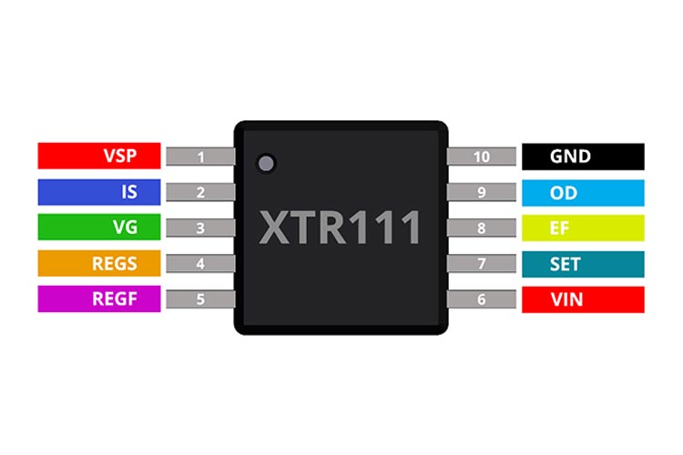
XTR111 Pinout Configuration
|
Pin |
Name |
Function |
|
1 |
VSP |
Positive Supply |
|
2 |
IS |
Source Connection |
|
3 |
VG |
Gate Drive |
|
4 |
REGS |
Regulator Sense |
|
5 |
REGF |
Regulator Force |
|
6 |
VIN |
Input Voltage |
|
7 |
SET |
Transconductance Set |
|
8 |
EF |
Error Flag (Active Low) |
|
9 |
OD |
Output Disable (Active High) |
|
10 |
GND |
Negative Supply |
Features
- Easy to Design Input /Output Ranges: 0mA–20mA, 4mA–20mA, 5mA–25mA and voltage outputs.
- Nonlinearity: 0.002%
- Low offset drift: 1μV/°C
- Accuracy: 0.015%
- Single supply operation
- Wide supply range: 7V to 44V
- Output Error flag
- Output disable pin
- Adjustable voltage regulator: 3 – 15V
Other Popular Voltage–Current Converter ICS
XTR110, AM402
Note: Complete technical details can be found in the XTR111 datasheet at this page’s end.
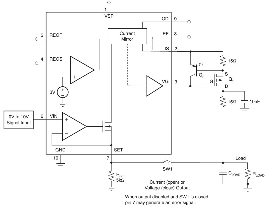
How To Use XTR111?
The image below shows the typical application diagram for the XTR111. The circuit below is capable of generating 0-10V or 0-20mA output depending on the state of switch SW1. If it is open the XTR111 will act as a current source and can be used to out put the current from 0-20mA. With the switch is closed we can use it to generate variable voltage.
Applications
- Universal voltage controlled current source.
- Voltage or current output for 3-wire sensor system
- PLC output programable driver
- TETRA Base Stations
- Current Mode sensor excitation
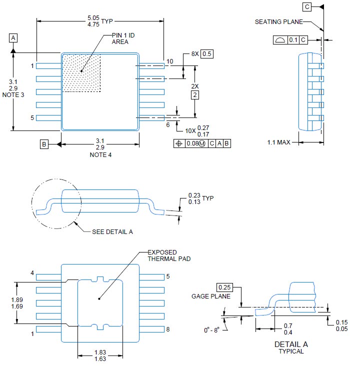
2D Model and Dimensions
Below is the 2D CAD drawing of XTR111 along with its dimensions in inches [millimetres]. The dimensions can be used to create custom footprints of the module and be used for PCB or CAD modeling.