TC4584 Hex Schmitt Trigger

The TC4584B is the 6 circuit inverter having the Schmitt trigger function at the input terminal. TC4584B can be used in the broad range application including line receiver, waveform shaping circuit, astable multivibrator, monostable multivibrator in addition to an ordinary inverter.
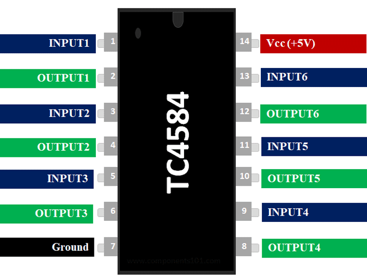
Pin Description of TC4584B:
|
Pin Number |
Pin Name |
Description |
|
1,3,5,11,13,15 |
Schmitt Input Pins |
Input pins of the Schmitt trigger |
|
2,4,6,10,12,14 |
Schmitt Inverted Output Pins |
Output pins of the Schmitt trigger |
|
7 |
Ground |
Connected to the ground of the system |
|
14 |
Vcc (+5V) |
Resets all outputs as low. Must be held high for normal operation |
Features of TC4584B:
- Schmitt Trigger – Hex Inverter
- Operating Voltage: 5V
- Output current High: -9mA
- Output current Low: 15mA
- Hysteresis voltage: 0.65V
- Power dissipation: 180mW
- Propagation Delay Time: 170 ns
- Operating Temperature Range: -40 C to + 85 C
- Available in 14-pin DIP, SOIC packages
Note: Complete Technical Details can be found at the TC4584B datasheet give at the end of this page.
Equivalent for TC4584: MC14584B, NTE4584B
Alternatives Schmitt Triggers: SN74LS14, TC4584, CD40106
Where to use TC4584:
The TC4584 is a Hex Schmitt Trigger in a 14−Lead DIP/SOP type package constructed with MOS P−Channel and N−Channel enhancement mode devices in a single monolithic structure. TC4584 IC primarily used where low power dissipation and high noise immunity are desired. It is also used to “square up” slowly changing waveforms. A Schmitt trigger is also useful for debouncing a push button or other noisy input devices.
So if you are looking for an IC which can help you to get of switching noise or to create sharp square wave signals based on an input signal then this IC could be the right choice or you.
How to Use TC4584:
As mentioned earlier TC4584 has six inverting Schmitt trigger gates which can be used as six individual gates. TC4584 internal structure is given below:
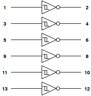
Each of these 6 gates can be used individually based on our application. Since the gates are inverting we can also combine two gates to form a non-inverting gate. The input signal can be a noise square wave or any signal wave that oscillates between the low and high hysteresis voltage.
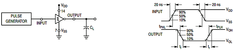
The unique and special functionality of a Schmitt trigger is to toggle the output based on the input signal without any noise. This is achieved by using a hysteresis band inside which no switching takes place. Switching Time Test Circuit and Waveform is given below:
Applications of TC4584B
- Noise removing circuits
- Debouncing circuits
- Hysteresis controller
- Dead band filter
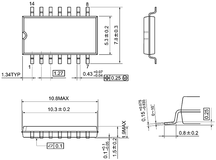
2D Model of TC4584B (SOP)
Dimensions for TC4584B IC is given below. These dimensions are for the SOP package. If you are using different package IC please refer to TC4584B datasheet.