OB3350CP LED Driver IC
The OB3350 is a LED Driver IC that is commonly used in powering the backlight of LCD/LED displays or to drive sensitive LEDs at constant current. The IC consists of a PWM boost driver that could regulate constant current through an LED using current mode control and fixed frequency operation. The IC is commonly used with power switches like MOSFET to driver LEDs.
Pin Configuration
|
Pin Number |
Pin Name |
Description |
|
1 |
Vin |
This is the power supply input, where the recommended operating range is 8V to 35 V DC. |
|
2 |
GATE |
It is the gate driver output pin which can be connected to the MOSFET (acts like a switch) to either allow the required LED current or else blocks it by turning off the input at gate terminal. |
|
3 |
GND |
This is the power ground terminal. |
|
4 |
CS |
The Current sense terminal gets the LED current and based on its intensity the gate driver output (GATE terminal) will be altered. |
|
5 |
FB |
It is the LED current feedback input terminal which is used to monitor the intensity of current flowing through the device so that the current can be balanced to avoid damaging the external device. |
|
6 |
COMP |
It is the Boost Converter Loop compensation terminal which is used to control the inductor current based on the type of load used. |
|
7 |
OVP |
The Over Voltage Protection terminal monitor the LED currents, if they go beyond the threshold levels, if any such conditions are found it resets the Vin or PWM signal to avoid the external LED getting damaged. |
|
8 |
PWM |
PWM stands for Pulse Width Modulation, with respect to OB3350CP, it is used to control the brightness of the LED. An external PWM signal of frequency range 100Hz to 1KHz and voltage range of 0V to greater than 2.5V can be applied to this pin. |
Specifications
- Operating Voltage: 8V to 35V
- Burst Dimming frequency: 100Hz to 1KHz
- Operating supply current: 3 mA (max)
- Stand by current: 400 µA (max)
- PWM operating frequency: 175 KHz to 275 KHz
- PWM input threshold (low): 1.3 V (min)
- PWM input threshold (high): 2.5 V (max)
- Threshold of output over voltage : 1.8V (min), 2.2V (max)
Features
- Current Mode PWM Controller With Good Dynamic Response
- 8V to 35V Input Voltage Range
- External PWM Dimming Mode
- Over Voltage Protection
- Over Current Protection
- Under Voltage Lockout (UVLO)
- Thermal Shutdown
Alternative to OB3350: BP3316D, SSL5015
Other Display Driver IC: LM3914, LM3915, MAX7219
Working of OB3350CP
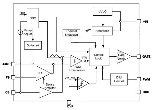
The block diagram of the OB3350CP is as below:

The control logic is the heart of the IC OB3350CP, all the functionalities that are need to be done will be processed at the control logic. When the sufficient voltage is applied to the VIN terminal (min. of 7V) the UVLO (Under Voltage Lockout) block checks for the voltage to be 7.5V when it is 7.5V, IC starts its switching operation, when the voltage falls under 7V it stops its operation till it gets back to 7.5V.
The thermal shutdown block detects the typical temperature conditions, if it exceeds the threshold temperature the IC gets automatically turned OFF. The oscillator generates a ramp wave to run the control logic as well as to maintain the duty cycle of the PWM signal.
The CS (Current Sense input), COMP (Compensation terminal), FB (Feedback sense input are used to sense the load currents and then to stabilize them from being crossing the threshold values. All these modified values are again feedback to the control logic block to perform the relevant action.
An external PWM signal can also be used to control the LED current with the help of DIM control block which is fed to the control logic so that the driver goes high or low based on the threshold value.
The OVP (Over Voltage Protection) block has a maximum threshold voltage of 2.2V, when the voltage level of the PWM signal falls this threshold value, the control logic shuts down the system. So, the OB3350CP has all the safety measures in order to maintain the current stable and avoid damage of the LEDs or LED backlights etc.
How to use OB3350CP
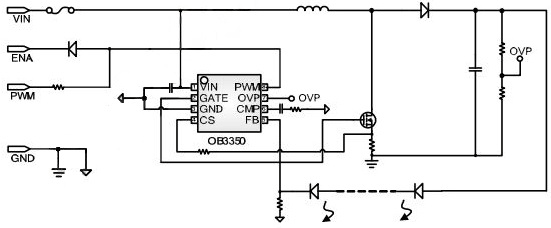
The typical application of the IC is as below:

A MOSFET can be used as a switch to control the flow of the LED current. The GATE terminal of the IC is fed to the gate terminal of the MOSFET. So in any emergency conditions the over LED current can be stopped. The Drain current from the MOSFET is fed back to the sensing elements to maintain the stability of the upcoming output current.
The inductor here is used to allow only the DC currents so that the load LED does get damaged due to the alternating currents. With the simple potential divider circuit using resistors the OVP voltage can be determined; when it falls below the threshold voltage the output will be disabled.
Applications
- LCD monitor
- LCD TV
- Flat panel display
- LED driver circuits are few applications of the OB3350CP
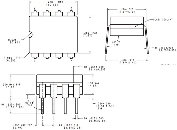
2D-Model


