MAX98357 Low Cost PCM 3W Class D Amplifier
The MAX98357A/MAX98357B is an easy-to-use, low-cost, digital Class D amplifier designed for PCM (Pulse Coded Modulation) input, offering industry-leading Class AB audio performance with Class D efficiency. With its versatile digital audio interface, it automatically recognizes up to 35 different PCM and TDM clocking schemes, eliminating the need for I2C programming. The amplifier simplifies operation by removing the requirement for an external MCLK signal used in PCM communication, reducing EMI and potential board coupling issues. Both the MAX98357A and MAX98357B support 8-channel time division multiplexed (TDM) data, with the MAX98357A supporting I2S data and the MAX98357B supporting left-justified data. The digital audio interface accepts specified sample rates between 8kHz and 96kHz for all supported data formats. These ICs can be configured to output left channel, right channel, or a combined (left/2 + right/2) output from the stereo input data. Operating with 16/24/32-bit data in I2S and left-justified modes, as well as 16-bit or 32-bit data in TDM mode, they deliver flexibility in audio processing.
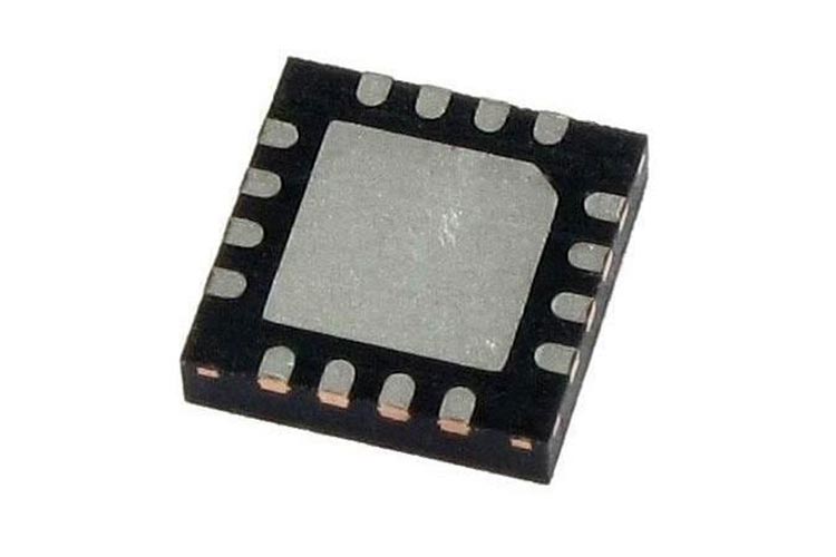
The MAX98357A/MAX98357B amplifiers are available in 9-pin WLP (1.345mm x 1.435mm x 0.64mm) and 16-pin TQFN (3mm x 3mm x 0.75mm) packages. Overall, these amplifiers provide cost-effective, high-quality audio solutions with efficient performance, simplified operation, and a wide range of supported data formats.
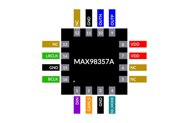
MAX98357 Pinout Configuration
|
Pin |
NAME |
FUNCTION |
|
4 |
SD_MODE |
Shutdown and Channel Select. Pull SD_MODE low to place the device in shutdown. In I2S |
|
7, 8 |
V DD |
Power-Supply Input |
|
9 |
OUTP |
Positive Speaker Amplifier Output |
|
1 |
DIN |
Digital Input Signal |
|
2 |
GAIN_ |
Gain and Channel Selection. In I2S and LJ mode determines amplifier output gain (Table 8) |
|
10 |
OUTN |
Negative Speaker Amplifier Output |
|
16 |
BCLK |
Bit Clock Input |
|
3, 11, 15 |
GND |
Ground |
|
14 |
LRCLK |
Frame Clock. Left/right clock for I2S and LJ mode. Sync clock for TDM mode. |
|
5, 6, |
N.C. |
No Connection |
|
— |
EP |
Exposed Pad. The exposed pad is not internally connected. Connect the exposed page to a |
Features
- Single-Supply Operation (2.5V to 5.5V)
- 3.2W Output Power into 4Ω at 5V
- 2.4mA Quiescent Current
- 92% Efficiency (RL = 8Ω, POUT = 1W)
- 22.8µVRMS Output Noise (AV = 15dB)
- Low 0.013% THD+N at 1kHz
- No MCLK Required
- Sample Rates of 8kHz to 96kHz
- Supports Left, Right, or (Left/2 + Right/2) Output
- Sophisticated Edge Rate Control Enables Filter less Class D Outputs
- 77dB PSRR at 1kHz
- Low RF Susceptibility Rejects TDMA Noise from GSM Radios
- Extensive Click-and-Pop Reduction Circuitry
- Robust Short-Circuit and Thermal Protection
Other Popular PCM Amplifier Chips
MAX98355, MAX98360, MAX98361
Note: Complete technical details can be found in the MAX98357 datasheet at this page’s end.
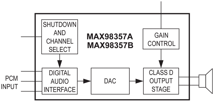
Block Diagram
Application Circuit
The following image shows the typical application circuit for the MAX98357.
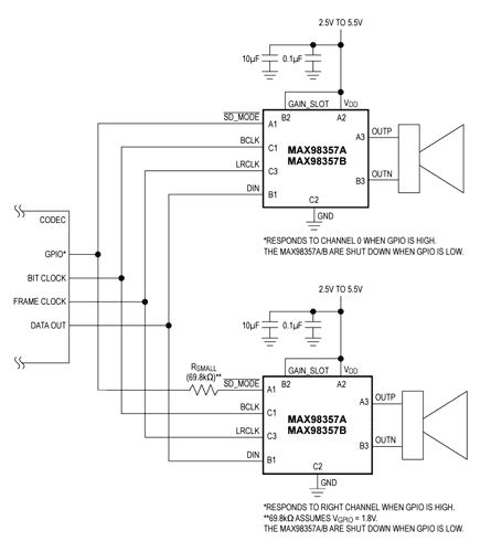
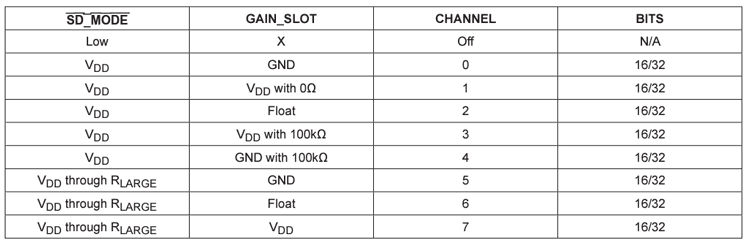
The MAX98357 requires only bare minimum auxiliary components. Two bypass capacitors and a resistor for channel selection. When the SD_Mode pin is connected directly to GPIO and it’s in high state, the MAX98357 will respond to left channel, while if there is a 69.8KOhms resistor in between the MAX98357 will respond to the right channel. If the SD_Mode pin is pulled low the MAX98357 will be in shutdown state. Using SD_Mode and Gain_Slot pin combinations we can select which channel the MAX98357 will respond to. Please refer to the table below for the possible combinations.
Applications
- Cameras
- Gaming Devices (Audio and Haptics)
- IoT Devices
- Notebook Computers
- Single Li-ion Cell/5V Devices
- Smart Speakers
- Smartphones
- Tablets
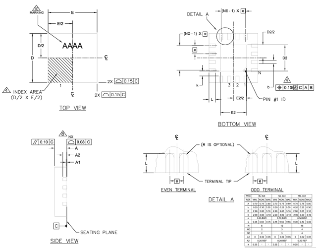
2D-Model and Dimensions
Below is the 2D CAD drawing of MAX98357 TQFN along with its dimensions in millimetres. The dimensions can be used to create custom footprints of the module and be used for PCB or CAD modeling.