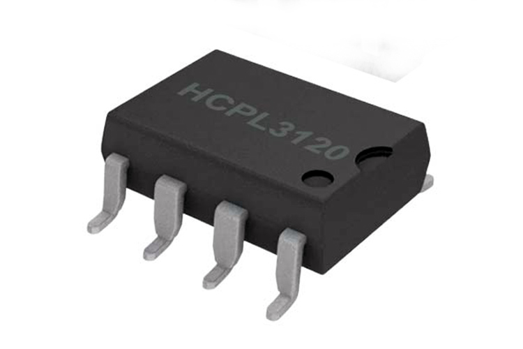
HCPL3120 Gate Drive Optocoupler
In high power applications, IGBTs and MOSFETs are widely used. These parts are often switching high voltages, in the order of hundreds of volts, in noisy environments. For this reason, it is often preferable to have the gate drive signals isolated from the high voltage switching side. The HCPL3120 is a gate driver that has built-in optical isolation, which helps in keeping high common-mode voltages away from the control electronics with the added advantage of having the possibility to float the gate drive voltage.
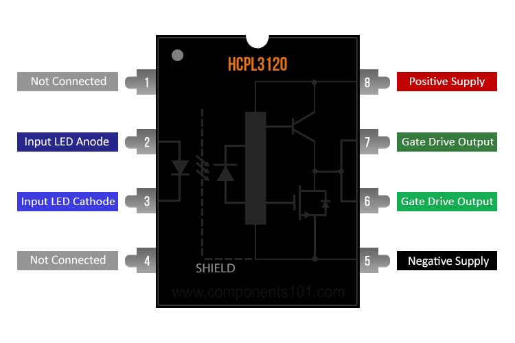
HCPL3120 Pinout Configuration
|
Pin Number |
Pin Name |
Description |
|
1, 4 |
NC |
Not connected |
|
2 |
ANODE |
Input LED anode |
|
3 |
CATHODE |
Input LED cathode |
|
5 |
VEE |
Negative supply pin |
|
6, 7 |
VO |
Gate drive output pin |
|
8 |
VCC |
Positive supply pin |
Features and Specifications
- 2A minimum and 2.5A maximum output current
- Undervoltage lockout protection with hysteresis
- 15V to 30V supply
- 500ns switching speeds
Note: Complete technical details can be found in the HCPL3120 datasheet given at the end of this page.
HCPL3120 Equivalents
HCNW3120
Other Gate Drivers
TC4420, TC4427
How To Use HCPL3120?
MOSFET and IGBT gates present a capacitive load that has to be charged and discharged quickly to turn the device on and off at high switching speeds, keeping it out of the linear region where conduction losses are high and also preventing switching losses. For this reason, dedicated gate drive ICs are used, which converts the logic levels of the gate drive signal to higher voltages suitable to drive MOSFETs and IGBTs, while at the same time having a higher current capability.
The HCPL3120 also provides additional galvanic isolation, meaning that the logic input side and the gate drive side are completely isolated from each other. This is done using an internal optocoupler, whose input is an LED, and the output connects to a high-current push-pull driver. A simple application circuit is shown below.
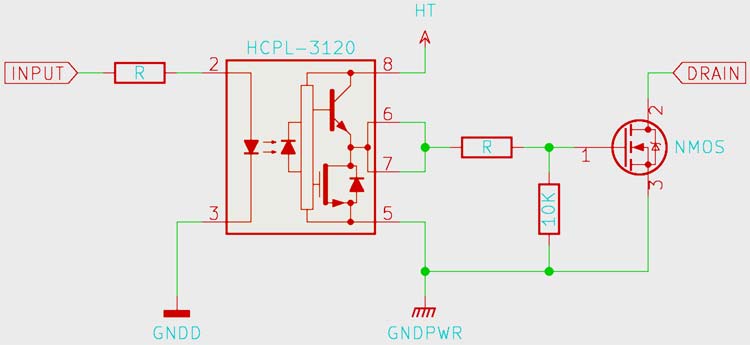
Decoupling the HCPL3120 is very important, since the current draw spikes when the gate is being charged and discharged. Ceramic capacitors are the best choice. The resistor limiting the current to the input LED is calculated so that at least 5mA flows through the LED, whose threshold is around 2.5mA. 10mA is also preferable. An output resistor has been added between the gate of the MOSFET being driven and the IC to protect both against large current spikes while switching. A pull-down resistor is also good practice since it keeps the MOSFET/IGBT gate discharged when the circuit is not powered on.
Applications
- IGBT/MOSFET gate drive
- AC and brushless DC motor drives
- Inverters
- Switch mode power supplies
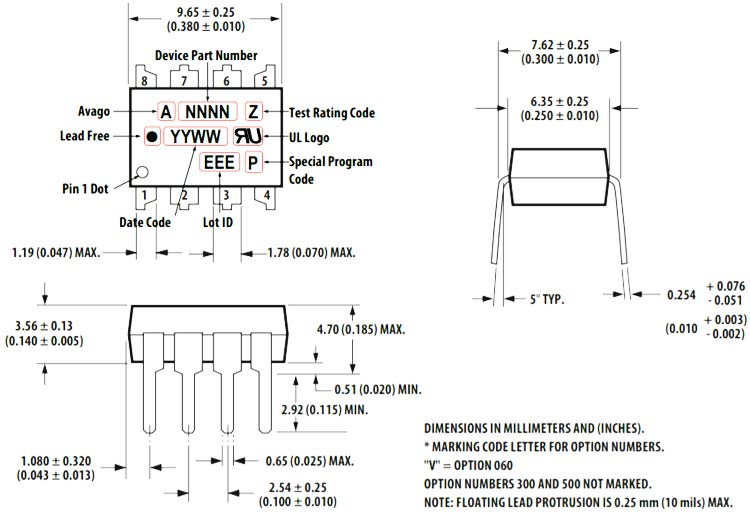
2D Model and Dimensions
If you are designing a PCB or Perf board with this component then the following picture from the Datasheet will be useful to know its package type and dimensions.