H1102NL Ethernet Transformer IC
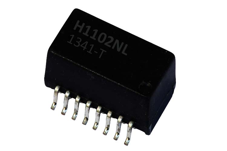
Ethernet is a wired networking technology that makes use of twisted pair differential cables to transfer data at high bitrates. Because of the distances over which it can be transported, various effects like static charge and common mode noise are picked up. To prevent this from affecting the transmitting and receiving circuits, a component called an ethernet transformer is used. The H1102NL is one such transformer, containing a pair of magnetics inside for both transmitting and receiving sections as well as common mode protection.
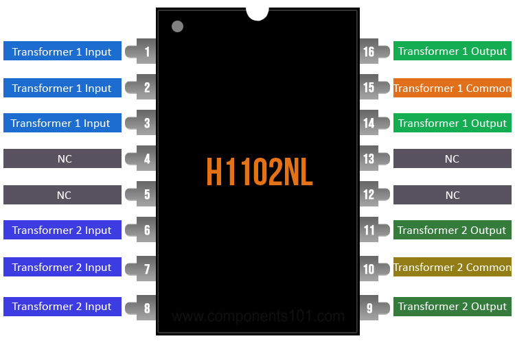
H1102NL Pinout Configuration
|
Pin Number |
Pin Name |
Description |
|
1, 2, 3 |
Transformer 1 inputs |
Signal input pins for the first transformer |
|
6, 7, 8 |
Transformer 2 inputs |
Signal inputs for the second transformer |
|
15 |
Transformer 1 common |
Secondary common for the first transformer |
|
10 |
Transformer 2 common |
Secondary common for the second transformer |
|
16, 14 |
Transformer 1 outputs |
Signal output pins for the first transformer |
|
11, 9 |
Transformer 2 outputs |
Signal output pins for the second transformers |
Features and Specifications
- Dual transmit/receive magnetics
- Conforms to IEEE802.3 specification
- Compact footprint
Note: Complete technical details can be found in the H1102NL datasheet given at the end of this page.
H1102NL Equivalents
H1183NL, H1199NL
Other
H11XX Series
How To Use H1102NL?
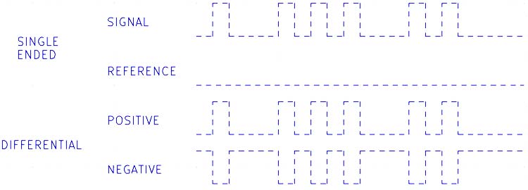
The Ethernet protocol uses differential signaling, i.e. instead of one signal and one reference wire, two wires are used, whose states are complementary to each other, as shown in the figure below. This makes the signal more immune to common-mode noise.
Ethernet cables are usually run over long distances. This increases the chance of picking up noise from mains, high-frequency switching converters, and other sources of electromagnetic noise. The plastic insulating cable can also generate static charges, which can result in harmful high-voltage arcing which can damage the transmitting and receiving electronics.
For this reason, an isolating transformer is used on both the transmitting and receiving sides of the circuit. The primary side has two windings that share a common terminal. The middle terminal is connected to VDD in case the transmitting IC has open-drain outputs, and is left floating in case of push-pull outputs. Each of the outer pins is connected to the differential negative and positive outputs of the transmitting IC. A similar scheme is followed on the secondary side, but the center tap is connected to either ground or a reference voltage that is generated on the receiving side.
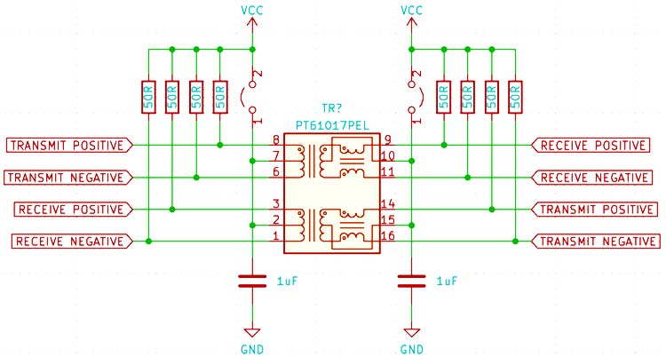
There is also a coupled inductor on the secondary side that acts as a common mode choke, which blocks signals related to earth ground but lets differential signals pass through.
Applications
- Ethernet LAN, MAN, and WAN networks
- PoE (Power over Ethernet)
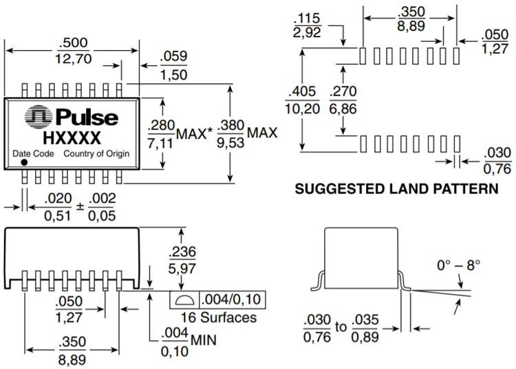
2D Model and Dimensions
If you are designing a PCB or Perf board with this component then the following picture from the Datasheet will be useful to know its package type and dimensions.