CD4518 Dual BCD Up Counter IC
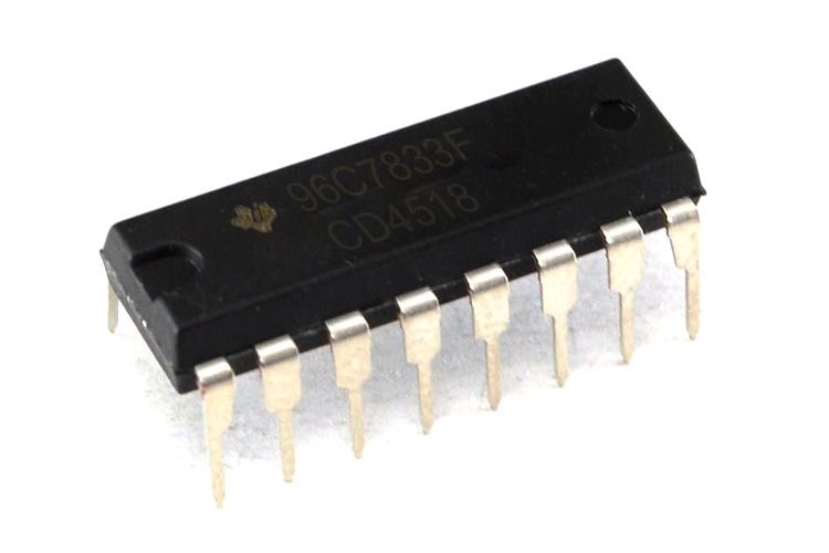
CD4518 IC is a BCD Up counter consisting of two individual synchronous Up counters. The IC is made from D-type flip-flops and has an interchangeable CLOCK and ENABLE pin. Up counter IC has various applications and can be used for timing-related projects.
Features and Specifications
This section mentions some of the features and specifications of CD4518 IC.
- Supply Voltage(VDD): -0.5V - 20V DC
- Positive or Negative Edge Triggering
- 6MHz Typical Clock Frequency at 10V
- Parametric Ratings: 5V, 10V, and 15V
Note: More technical information can be found in the CD4518 Datasheet, linked at the bottom of this page.
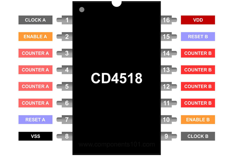
CD4518 Pinout Configuration
The CD4518 IC has 16 pins in total. The table below can be referred to understand the pin configuration of the IC.
|
Pin Number |
Pin Type |
Pin Description |
|
1 |
Clock A |
Clock Input A |
|
2 |
Enable A |
Enable line A |
|
3 |
Q1A |
Counter A |
|
4 |
Q2A |
Counter A |
|
5 |
Q3A |
Counter A |
|
6 |
Q4A |
Counter A |
|
7 |
Reset A |
To Reset counter A |
|
8 |
VSS |
Ground |
|
9 |
Clock B |
Clock Input B |
|
10 |
Enable B |
Enable line B |
|
11 |
Q1B |
Counter B |
|
12 |
Q2B |
Counter B |
|
13 |
Q3B |
Counter B |
|
14 |
Q4B |
Counter B |
|
15 |
Reset B |
To Reset Counter B |
|
16 |
VDD |
Positive supply Input |
Dual BCD Up Counter IC Working
The CD451 Up counter consists of two identical synchronous 4-stage counters. The image below shows the logic circuit of the BCD Up counter.
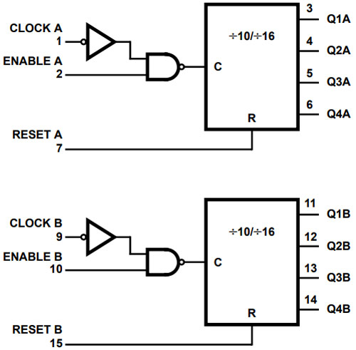
The counter stages are the D-type flip-flops having interchangeable CLOCK and ENABLE lines for incrementing the positive or negative-going transition, For the operation of a single unit, the ENABLE input is kept HIGH and the counter advances each positive-going transition of the CLOCK. The RESET lines clear out the HIGH levels.
Alternatives
7490, 74163, CD74HC4518E
Available Packages
Braze Seal DIP, Frit Seal DIP, Ceramic Flatpack
Applications
Here are some of the applications of the CD4518 IC.
- Pulse counter
- Counter circuits
- Multistage Ripple Counting
- Timing related projects
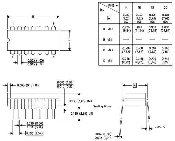
2D Model
Below is the 2D model of the CD4518 IC along with its dimensions in inches(millimeters). The following information can be used to design custom footprints of the IC and be used while PCB designing and CAD modelling.