CD4022 Divide by 8 Counter IC
CD4022 is TTL logic Octal Counter IC. It has eight output pins which increments from zero to eight for every input clock pulse. The maximum clock frequency is 5Mhz and is commonly used in digital counters, LED drivers, and other digital arithmetic applications.
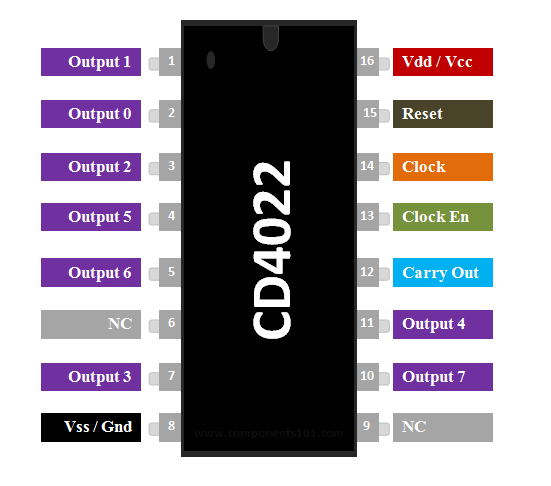
Pin Configuration
|
Pin Number |
Pin Name |
Description |
|
1 to 6 and 7,10,11 |
Output pins 0 to 7 |
These are the 8 output pins on which the counting occurs, they are not in order hence verify pin diagram above |
|
8 |
Vss or Ground |
Connected to the Ground of the circuit |
|
12 |
Carry Out (CO) |
This pin goes high after the IC counts from 1 to 10. This is used as carry while counting. |
|
13 |
Clock Enable (EN) |
This is an input which when made high will hold the count at the current state |
|
14 |
Clock |
The counting happens when this clock pulse goes high , this pin is normally connected to 555 timer or other uC to produce a pulse |
|
15 |
Resets |
As the name suggests this pin resets the count back to 1 |
|
16 |
Vdd / Vcc |
Connects to the supply voltage typically +5V |
Features
· High speed 16 pin CMOS Decade counter
· Supports 10 decoded outputs
· wide supply voltage range from 3V to 15V, typically +5V
· TTL compatible
· Operating Clock Frequency: 5 Mhz
· High Level Output Voltage: 4.5V @5V Vcc
· High Level Output current: 0.36mA
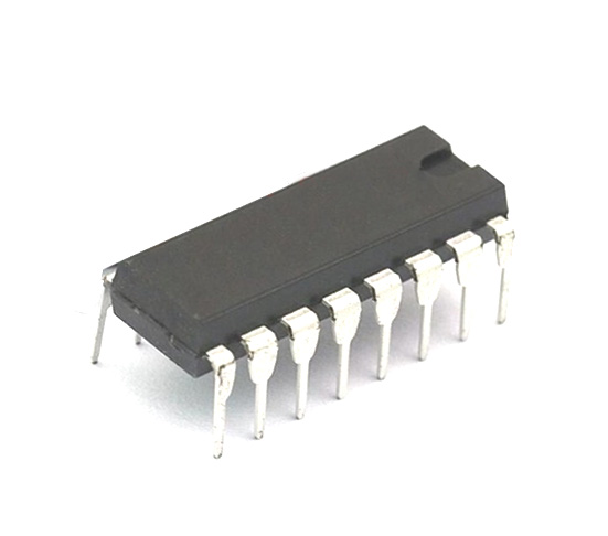
· Available in 16-pin PDIP, GDIP, PDSO packages
Note: Complete Technical Details can be found at the CD4022 datasheet given at the end of this page.
Alternatives Counters
IC4040, IC4060, IC4017
Where to use CD4022 IC
The IC CD4022 is used for counting applications, it has the capability to turn on 8 outputs sequentially in a pre-defined time and reset the count or hold it when required. It also has the capability to indicate the status of counting using Carry pin. This is commonly used for LED chasers and other logical output projects, where you need to perform arithmetic operations. It is also called as Divide by 8 Counter since the carry pin produces one clock pulse for every 8 pulses on the clock pin. So if you are looking for a sequential decoded counting IC that can count up to 8 then this IC will be your right choice.
How to use a CD4022 IC
The IC can work from 3V to 15V, but normally powered with +5V to the Vdd/Vcc pin and the Ground/Vss pin is connected to ground. We have 8 output pins ranging from Q0 to Q7, these pins can be connected to any load but we are using LEDs here as shown in the circuit below.
This IC will increment the count from 0 to 7 (Q0 to Q7) each time it senses a high pulse from the clock pin (pin 14). So we need a clock source to keep this IC ticking, this clock source can be a simple 555 Timer circuit that could generate pulse or a microcontroller like Arduino, PIC etc to generate our custom pulse using I/O pins.
The output changes sequentially from Q0 to Q7 for every high pulse from the Clock pin, but this sequence can be interrupted by two pins. They are the Clock Enable (pin 13) and Reset (pin 15) pins. These pins are held low (0V/grounded) by default, but when the Clock Enable pin is made high the counting pauses. For example if the count was at pin Q3 when the Clock enable pin was made high, then the count will pause at pin Q3 irrespective of any high pulses from clock and will continue incrementing only when Clock Enable is made low again. Similarly, if the reset pin is made high. The count will reset itself back to Q0 and will stay there until reset is made low again.
We have another pin called the carry out pin (12th pin), this pin will stay low (0V) by default. But when the IC completes counting up to 10, the pin will go high and will remain high till it counts till 4, when its 4 it will go down (0V) and turn on again when it reaches 8 as show in the simulation above. This helps the IC to be easily cascaded with other IC.
Since the CD4022 is based on TTL logic it is easy to use this IC in combination with other digital ICs like Flip-Flops, Logic Gates etc. The complete working of the IC can be found in the video linked below.
Application
· Used in LED matrix, LED chaser and other LED projects
· Binary counter or Binary decoder
· Can be used for divide by N counting
· remote metering, automotive, medical electronic
· Instrumentation and Alarm systems
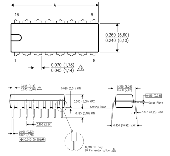
2D Model of CD4017 (PDIP)