CA3130 MOSFET Op-Amp
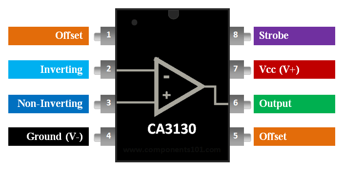
Pin Configuration
|
Pin Number |
Pin Name |
Description |
|
1,5 |
Offset Null Pins |
Optionally used to remove the offset voltage at the output pin to make it perfect 0V during off state. |
|
2 |
Inverting Input (IN-) |
The Inverting pin is also given a fixed voltage which is compared with the (IN+) |
|
3 |
Non-Inverting Input (IN+) |
The Non-Inverting Pin of the comparator is give a variable voltage to compare |
|
4 |
Ground (VCC-) |
This pin is connected to the ground of the system (Negative voltage can also be used) |
|
6 |
Output |
This is the output pin of the op-amp |
|
7 |
VCC+ |
Provide the operating voltage for the Op-Amp. For CA3130 it is upto +16V |
|
8 |
Strobe |
Allows you to turn off output stage |
CA3130 Specifications
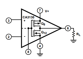
- Op-amp coupled with MOSFET at output
- Wide power supply Range
- Singe supply – 5V to 16V
- Dual supply – ±2.5V to ±8V
- Input Terminal current: 1mA
- Maximum Output Voltage: 13.3V
- Maximum source current: 22mA
- Maximum sink current: 20mA
- Supply current: 10mA
- Common Mode Rejection Ration (CMRR): 80dB
CA3130 Equivalent/Substitute
Alternatives Comparator Op-Amp IC
LM311,LM741, LM358, LM339, LM324
Where to use the CA3130 Comparator Op-Amp
The CA3130 is a BiMOS Operational Amplifier with MOSFET. The term BiMOS implies that it combines the advantage of both Bipolar and CMOS op-amp technology. Bipolar op-amps perform well under high bandwidths (fast switching) and CMOS op-amps perform well by consuming less current. So the CA3130 being a BiMOS op-amp has the advantage of high bandwidth operation and less current consumption.
The op-amp is built using MOSFETS and hence it has high input impedance. Meaning, when a sensor’s output voltage is connected to the inverting or non-inverting pin of the op-amp, the op-amp will not act as a load to the sensor and thus the output voltage from sensor will not be disturbed. So if you are looking for a Op-amp with high bandwidth, fast sample rate, less power consumption and high input impedance then this op-amp might be the right choice for you
How to use CA3130
Like all voltage Comparators the CA3130 also has an Inverting Pin and a Non-Inverting Pin. If the voltage at the Non-Inverting Terminal (pin 3) is high than the Inverting Terminal (pin 2) the output (pin 7) will also be high else the output will be low.
The CA3130 can work in a Single supply voltage or in a dual supply mode. For now let’s concentrate on the +5V supply voltage circuit since this is the most used design for digital circuits. In this type, the VCC+ (pin 8) is connected to +5V supply voltage and the VCC (pin 4) is grounded to hold it at 0V potential. A sample circuit is shown below
The special ability of this op-amp is to work with high frequencies; it has a CMRR of 80dB and the rise time is as low as 0.09uS. This makes it ideal for voltage followers and other switching related applications
Applications
- Frequency Generator/Distorter
- Mobile jammers
- Voltage follower circuits
- DAC circuits
- Peak Signal/Noise detectors
- Oscillator circuits
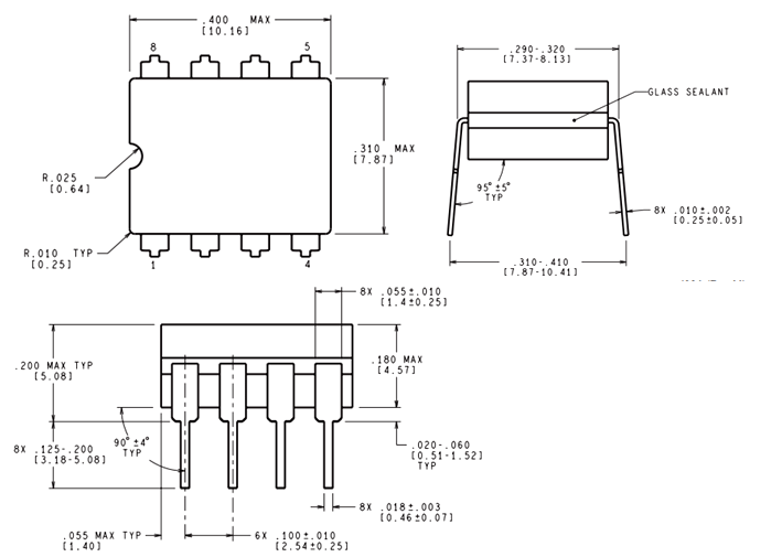
2D-Model