BQ27220 - Single-Cell Fuel Gauge IC


The BQ27220 is a high-precision low-power fuel gauge IC manufactured by Texas Instruments. The BQ 27220 device uses the Compensated End-of Discharge Voltage (CEDV) algorithm to monitor the battery parameters. It is capable of monitoring the remaining battery capacity (mAh), state-of-charge (%), runtime-to-empty (min), battery voltage (mV), temperature (°C), and state-of-health (%). The BQ27220 uses only 50 μA normally and it goes down to 9 μA in sleep mode, so this is perfect for battery operated applications. The IC communicates over an I2C interface, making it easy to interface with various microcontrollers. There are two options for setting Compensated End of Discharge Voltage (CEDV) parameters. You can use the pre-loaded values stored in the device's Read-Only Memory (ROM). Or you can create custom parameters using TI's online tool called GAUGEPARCAL. These custom settings can be uploaded to the device's RAM by the host system during startup, or permanently stored in the on-chip One-Time Programmable (OTP) memory by the user. The BQ27220 is available in tiny, 9-ball, 1.62 mm × 1.58 mm, 0.5-mm pitch Nano Free chip scale package (DSBGA) I which is ideal for space-constrained applications.
BQ27220 Pinout Configuration
Here we have only included the pinout details for the 6-pin DFN package.
| PIN NAME | PIN NUMBER | DESCRIPTION |
| BAT | C3 | LDO regulator input and battery voltage measurement input. |
| BIN | B1 | Battery insertion detection input. |
| GPOUT | A1 | open-drain output |
| SCL | A3 | Serial clock |
| SDA | A2 | Serial data |
| SRN | C2 | Coulomb counter differential inputs expect an external 10-mΩ, 1% sense resistor. |
| SRP | C1 | Coulomb counter differential inputs expect an external 10-mΩ, 1% sense resistor. |
| VDD | B3 | 1.8-V regulator output. Decouple with a 2.2-μF ceramic capacitor to VSS. This pin is not intended to provide power for other devices in the system. |
| VSS | B2 | Ground pin |
Manufacturers of BQ27220:
BQ27220 is manufactured by Texas Instruments.
BQ27220 Equivalents
If you're looking for Equivalents for BQ27220 then you can use BQ27426, it has the same pinout. But some functions may be different such as the algorithm used and others.
BQ27220 Alternatives
If you are looking for an equivalent or replacement for BQ27220 you can look at the other IC from these.
BQ27210, BQ27510, MAX17205
Note: Complete technical details can be found in the BQ27220 datasheet at this page’s end.
Features of BQ27220
BQ27220 has the following key features:
- Single-Cell Li-Ion Battery Fuel Gauge
- Resides in a Pack or on the System Board
- Supports Embedded or Removable Batteries
- Powers Directly from Battery with Integrated LDO
- Supports a Low-Value (10-mΩ) External Sense Resistor
- Ultra-Low Power Consumption in NORMAL (50 µA) and SLEEP (9 µA) Modes
- Battery Fuel Gauging Based on Compensated End-of-Discharge Voltage (CEDV) Technology
- Reports Remaining Capacity and State-of charge (SOC) with Smoothing Filter
- Adjusts Automatically for Battery Aging, Self-Discharge, Temperature, and Rate Changes
- Provides Battery State-of-Health (Aging) Estimation
- 400-kHz I2C Serial Interface
- Configurable SOC Interrupt OR Battery Low Digital Output Warning
- Internal Temperature Sensor OR Host-Reported Temperature OR External Thermistor.
BQ27220 Schematics
The following image shows the typical BQ27220 circuit diagram.
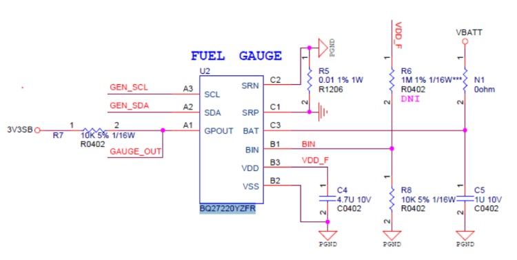
The BQ27220YFZR measures the battery voltage and current to accurately report the state of charge (SOC) and other battery parameters. The IC communicates with a host controller via the I2C bus (SDA and SCL lines) to report the battery status. GPOUT pin can be used to signal various conditions to the host, such as an alert for low battery. The BIN Pin is used to detect the presence of a battery by monitoring the voltage level on this pin. Capacitors C4 and C5 ensure that the power supply to the IC is stable and free of noise, which is crucial for accurate measurements. 3V3SB is a 3.3V supply rail. VBATT is the battery voltage input. R7 is used to Pull- the GPOUT pin. A current sense resistor(R5) is used for measuring the battery current.C1, C2, and C3 is used to decouple for the IC. R5 is connected between the battery and the SRP/SRN pins of the IC, used to measure the voltage drop across the resistor to determine the current flow.
Troubleshooting Tips for BQ27220
1. The fuel gauge shows the incorrect state of charge (SOC) or remaining capacity. How to solve this?
Ensure that the current sense resistor has the correct value and is properly connected. Calibration of the IC may be necessary. Verify that the resistor value matches the expected configuration in the device settings. complete a full discharge-charge cycle.
2. The I2C communication between the BQ27220 and the controller is unreliable or non-functional?
Check the pull-up resistors (GPOUT, SDA and SCL) to ensure they are of the correct value (typically 10kΩ). Verify the integrity of the connections and confirm that the I2C address is correctly set and not conflicting with other devices on the bus.
3. Why does the IC behave erratically or reset unexpectedly?
Ensure that the power supply is stable and within the operating range of the IC. Add decoupling capacitors close to the IC’s power pins to filter out noise and provide a stable voltage.
4. Why does the IC fail to detect the battery insertion correctly?
Ensure the BIN pin is correctly connected and that any required pull-up or pull-down resistors are properly installed. Verify that the BIN pin voltage levels are as expected for battery detection.
Design Tips for BQ27220
The battery connection on the BAT pin is used for two purposes:
- To supply power to the fuel gauge, and
- To provide an input for voltage measurement of the battery.
A capacitor of a value of at least 1 µF should be connected between BAT and VSS. The capacitor must be placed close to the gauge IC and have short traces to both the BAT pin and VSS.
The fuel gauge has an integrated LDO with an output on the VDD pin of approximately 1.8 V. A capacitor of a value of at least 2.2 µF should be connected between the VDD pin and VSS. The capacitor must be placed close to the gauge IC and have short traces to both the VDD pin and VSS. This regulator must not be used to provide power for other devices in the system.
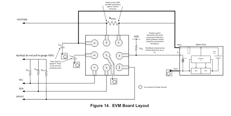
Layout Guidelines
- A capacitor of a value of at least 2.2 µF is connected between the VDD pin and VSS. The capacitor must be placed close to the gauge IC and have short traces to both the VDD pin and VSS. This regulator must not be used to provide power for other devices in the system.
- It is required to have a capacitor of at least 1.0 µF connected between the BAT pin and VSS if the connection between the battery pack and the gauge BAT pin has the potential to pick up noise. The capacitor should be placed close to the gauge IC and have short traces to both the BAT pin and VSS.
- If the external pullup resistors on the SCL and SDA lines will be disconnected from the host during low-power operation, it is recommended to use external 1-MΩ pulldown resistors to VSS to avoid floating inputs to the I2C engine.
- The value of the SCL and SDA pullup resistors should take into consideration the pullup voltage and the bus capacitance. Some recommended values, assuming a bus capacitance of 10 pF, can be seen in the table below.
| VPU | 1.8 V | 3.3 V | ||
| Range | Typical | Range | Typical | |
| RPU | 400 Ω ≤ RPU ≤ 37.6 kΩ | 10 kΩ | 900 Ω ≤ RPU ≤ 29.2 kΩ | 5.1 kΩ |
- If the host is not using the GPOUT functionality, then it is recommended that GPOUT be connected to a GPIO of the host so that in the cases where the device is in SHUTDOWN, toggling GPOUT can wake the gauge from the SHUTDOWN state.
- If the battery pack thermistor is not connected to the BIN pin, the BIN pin should be pulled down to VSS with a 10-kΩ resistor.
- The BIN pin should not be shorted directly to VDD or VSS.
- The actual device ground is pin B2 (VSS).
- The SRP and SRN pins should be Kelvin connected to the RSENSE terminals. SRP to the battery pack side of RSENSE and SRN to the system side of the RSENSE.
- Kelvin connects the BAT pin to the battery pack power terminal.
Applications of BQ27220
- Smartphones and Feature Phones
- Tablets
- Wearables
- Building Automation
- Portable Medical/Industrial Handsets
- Portable Audio
- Gaming
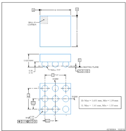
2D Model and Dimensions of BQ27220
Here you can find the mechanical drawings of BQ27220 along with its dimensions. The dimensions can be used to create custom footprints of the chip and be used for PCB or CAD modelling.