74HC157 – 2-Input Multiplexer IC
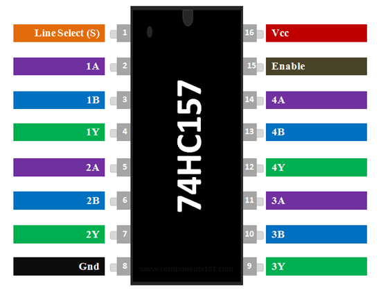
74HC157 Pin Configuration
|
Pin Number |
Pin Name |
Description |
|
2,5,11,14 |
Input A |
This is the first input line of the 2:1 Multiplexer |
|
3,6,10,13 |
Input B |
This is the second input line of the 2:1 Multiplexer |
|
4,7,9,12 |
Output Y |
This is the output line pin of the Multiplexer |
|
1 |
Line Select (S) |
The select pin selects one of the two input lines and gives it to output line |
|
15 |
Enable (E) |
Active low pin. Grounded for normal operation |
|
8 |
Ground |
Connected to the ground of the system |
|
16 |
Vcc |
This pin powers the IC, typically +5V is used. |
74HC157 IC Features
- 2-Input Multiplexer Quad Package
- Operating Voltage: 2V to 6V
- Minimum high-level Input Voltage: 3.15V @(Vcc=4.5V)
- Maximum low-level Input Voltage: 1.35V @(Vcc=4.5V)
- TTL/CMOS Input Logic compatibility
- Maximum Propagation Delay: 25ns @(Vcc=4.5V)
- Available in 16-pin PDIP, GDIP, PDSO packages
Note: Complete Technical Details can be found in the 74HC157 datasheet given at the end of this page.
74HC157 Equivalent
CY74FCT257T
Alternatives Multiplexer ICs
SN74LS153, 74LV4053, CD4053, MPC507AU
Where to use 74HC157 Multiplexer
74HC157 is a 2-input (2:1) Multiplexer IC. It has four similar multiplexers inside it and hence it is called as Quad package 2-Input Multiplexer. A Multiplexer as we know takes in 2 or more inputs and provides one of them as the output based on the Select line status.
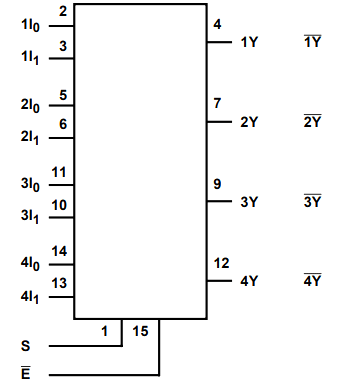
Similarly this IC has two input pins (Input I0 and Input I1) and one output pin (Output Y) which forms a 2:1 Multiplexer. Likewise there are 4 Multiplexers each of 2-inputs and 1-Output corresponding it, all these four Multiplexers are controlled through a single Line Select Pin (S) hence they cannot function independently. Hence if you are looking for a 2:1 Multiplexer IC with a quad package then this IC might be the right choice for you.
How to use the 74HC157 IC
Using the 74HC157 IC is pretty straight forward. The IC has an operating voltage of 2V to 6V so select the operating voltage (typically 5V is used) and then power the IC using the Vcc pin and the Ground pin. The Enable pin has to be connected to the ground for normal operation of the IC, so you can either ground it permanently or connected it to a MCU/MPU to turn on or of the Multiplexers as required.
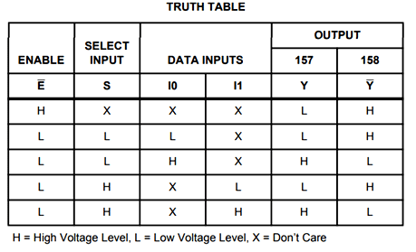
There are four 2:1 multiplexers in this IC, for simplicity let us consider we are using only one of the available four multiplexers. Since the multiplexer is a 2:1 Multiplexer it can take in two inputs, these two inputs are given to the pin Input A (a.k.a Input I0) and the pin Input B (a.k.a Input I1) the output of the multiplexer can be received from the output pin Y. The select line (pin 1) decides which of the two inputs should be given to the output pin. If the Select Line is low (logic 0) then Input A will be reflected on the output and if the select pin is high (logic 1) then the Input B will be reflected on the output pin Y. A working gif of 74HC157 IC is shown below.
As you can see out of the four multiplexers only the first multiplexer (1A, 1B and 1Y) is used for demonstration. The Enable pin of the IC is grounded and the select line pin (A’/B) is controlled using a logic state. When the Select pin is logic 0 the output line is connected to input A and when the select line is 1 the output pin is connected to Input B. The truth table showing all possible combinations of the inputs and outputs is shown below.
Applications
- Network lines
- Communication systems
- Small memory controllers
- Telephone line selector
- Computer memory
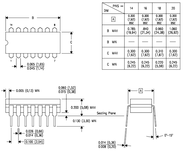
2D Model of 74HC157 (GDIP)