24C64 serial I²C bus EEPROM IC
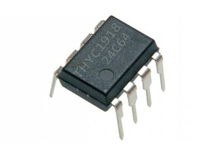
The 24C64 is an I2C-compatible 64-Kbit EEPROM IC that is organized as 8 K × 8 bits and has a clock frequency of up to 400 kHz. This I2C compliant IC can share a common 2 wire bus allowing up to 8 devices. The EEPROM IC has page-write capabilities of up to 32 bytes of data with data retention of more than 200 years. The 24C64 belongs to the AT24XX family where XX represents the number of memory bits, here in our case which is 64Kbit.
Features and Specifications
This section mentions some of the important features and specifications of the 24C64 EEPROM IC.
- Supply Voltage: 1.6V - 5.5V DC
- Compatible with all I2C bus modes: 1 MHz, 400 kHz, 100 kHz
- Memory array: 64 Kbit (8 Kbyte) of EEPROM
- Page size: 32 byte
- Byte Write within 5 ms
- Page Write within 5 ms
- More than 200 years of data retention
Note: More technical information can be found in the 24C64 EEPROM IC Datasheet, linked at the bottom of this page.
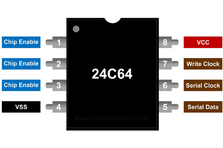
Pin Configuration
The 24C64 EEPROM IC has 8 pins. The table below explains the pin configuration of the EEPROM IC.
|
Pin Number |
Pin Type |
Pin Description |
Direction |
|
1 |
E0 |
Chip Enable |
Input |
|
2 |
E1 |
Chip Enable |
Input |
|
3 |
E2 |
Chip Enable |
Input |
|
4 |
VSS |
Ground |
- |
|
5 |
SDA |
Serial Data |
I/O |
|
6 |
SCL |
Serial Clock |
Input |
|
7 |
WC |
Write Clock |
Input |
|
8 |
VCC |
Voltage Input |
- |
Connecting 24C64 EEPROM IC to a Microcontroller/Microprocessor Unit
The EEPROM IC can be easily connected to an MCU/MPU. The diagram below can be referred to as the pinout and the connections of 24C64 to an MCU/MPU.
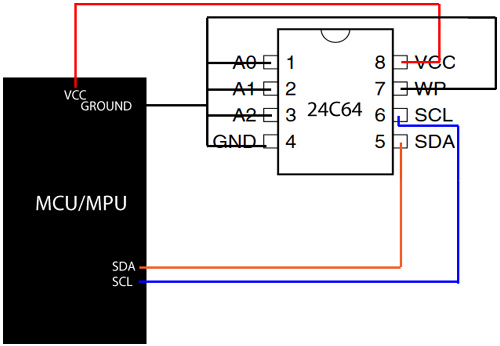
The 24C64 communicates via the I2C bus, so the SDA and the SCL pins are connected to the Data (I2C SDA) and clock(I2C SCK) line pin of the MCU/MPU, respectively. The SCA and SDA pins on the device are open rails so to make it work as normal pins you can also connect the pins to a pull-up resistor of 4.7K ohm and connect it to the VCC and then connect to your MCU.
The 3 pins A0, A1, and A2 form the address, so can be put to the ground. The WP/WC pin can be pulled down to the ground and the VCC and GND terminal of the 24C64 IC is to be connected to the VCC and Ground terminal of the MCU/MPU to power up the IC.
Note: You can connect the A0, A1, A2 pins to either VCC or Ground. These 3 pins decide the logic of the slave device. If you connect them to the ground, the logic is 0 and when you connect it to VCC the logic becomes 1.
Alternatives
Available Packages
PDIP(8), SO(8), TSSOP(8), UFDFPN(8), WLCSP(8)
Applications
Here are some of the applications of 24C64 EEPROM IC.
- Remote keyless systems
- Additional memory device
- Electronic appliances
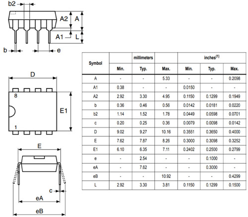
2D Model
Below is the 2D model of the 24C64 EEPROM IC along with its dimensions in millimeters. The following information can be used while designing custom footprints of the IC, which can be used for PCB designing and CAD modelling.