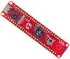
Altera DE2-115 Development Board
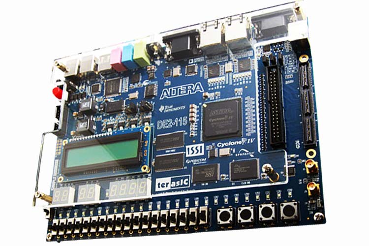
The DE2 series has consistently been at the forefront of educational development boards by distinguishing itself with an abundance of interfaces to accommodate various application needs. Extending its leadership and success, Terasic announces the latest DE2-115 that features the Cyclone IV E device. Responding to increased versatile low-cost spectrum needs to be driven by the demand for mobile video, voice, data access, and the hunger for high-quality images, the new DE2-115 offers an optimal balance of low cost, low power, and a rich supply of logic, memory, and DSP capabilities.
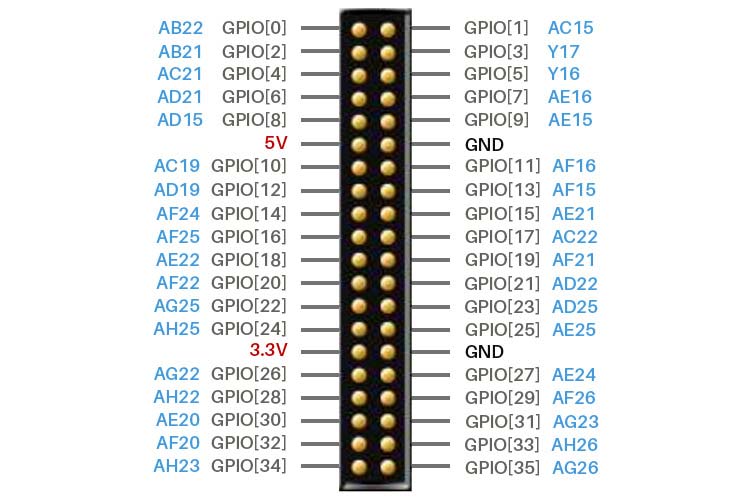
Altera DE2-115 Development Board Pinout
The DE2-115 Board provides one 40-pin expansion header. The header connects directly to 36 pins of the Cyclone IV E FPGA and also provides DC +5V (VCC5), DC +3.3V (VCC3P3), and two GND pins.
|
Signal Name |
FPGA Pin No |
Description |
I/O Standard |
|
GPIO[0] |
PIN_AB22 |
GPIO Connection DATA[0] |
Depending on JP6 |
|
GPIO[1] |
PIN_AC15 |
GPIO Connection DATA[1] |
Depending on JP6 |
|
GPIO[2] |
PIN_AB21 |
GPIO Connection DATA[2] |
Depending on JP6 |
|
GPIO[3] |
PIN_Y17 |
GPIO Connection DATA[3] |
Depending on JP6 |
|
GPIO[4] |
PIN_AC21 |
GPIO Connection DATA[4 |
Depending on JP6 |
|
GPIO[5] |
PIN_Y16 |
GPIO Connection DATA[5] |
Depending on JP6 |
|
GPIO[6] |
PIN_AD21 |
GPIO Connection DATA[6] |
Depending on JP6 |
|
GPIO[7] |
PIN_AE16 |
GPIO Connection DATA[7] |
Depending on JP6 |
|
GPIO[8] |
PIN_AD15 |
GPIO Connection DATA[8] |
Depending on JP6 |
|
GPIO[9] |
PIN_AE15 |
GPIO Connection DATA[9] |
Depending on JP6 |
|
GPIO[10] |
PIN_AC19 |
GPIO Connection DATA[10] |
Depending on JP6 |
|
GPIO[11] |
PIN_AF16 |
GPIO Connection DATA[11] |
Depending on JP6 |
|
GPIO[12] |
PIN_AD19 |
GPIO Connection DATA[12] |
Depending on JP6 |
|
GPIO[13] |
PIN_AF15 |
GPIO Connection DATA[13] |
Depending on JP6 |
|
GPIO[14] |
PIN_AF24 |
GPIO Connection DATA[14] |
Depending on JP6 |
|
GPIO[15] |
PIN_AE21 |
GPIO Connection DATA[15] |
Depending on JP6 |
|
GPIO[16] |
PIN_AF25 |
GPIO Connection DATA[16] |
Depending on JP6 |
|
GPIO[17] |
PIN_AC22 |
GPIO Connection DATA[17] |
Depending on JP6 |
|
GPIO[18] |
PIN_AE22 |
GPIO Connection DATA[18] |
Depending on JP6 |
|
GPIO[19] |
PIN_AF21 |
GPIO Connection DATA[19] |
Depending on JP6 |
|
GPIO[20] |
PIN_AF22 |
GPIO Connection DATA[20] |
Depending on JP6 |
|
GPIO[21] |
PIN_AD22 |
GPIO Connection DATA[21] |
Depending on JP6 |
|
GPIO[22] |
PIN_AG25 |
GPIO Connection DATA[22] |
Depending on JP6 |
|
GPIO[23] |
PIN_AD25 |
GPIO Connection DATA[23] |
Depending on JP6 |
|
GPIO[24] |
PIN_AH25 |
GPIO Connection DATA[24] |
Depending on JP6 |
|
GPIO[25] |
PIN_AE25 |
GPIO Connection DATA[25] |
Depending on JP6 |
|
GPIO[26] |
PIN_AG22 |
GPIO Connection DATA[26] |
Depending on JP6 |
|
GPIO[27] |
PIN_AE24 |
GPIO Connection DATA[27] |
Depending on JP6 |
|
GPIO[28] |
PIN_AH22 |
GPIO Connection DATA[28] |
Depending on JP6 |
|
GPIO[29] |
PIN_AF26 |
GPIO Connection DATA[29] |
Depending on JP6 |
|
GPIO[30] |
PIN_AE20 |
GPIO Connection DATA[30] |
Depending on JP6 |
|
GPIO[31] |
PIN_AG23 |
GPIO Connection DATA[31] |
Depending on JP6 |
|
GPIO[32] |
PIN_AF20 |
GPIO Connection DATA[32] |
Depending on JP6 |
|
GPIO[33] |
PIN_AH26 |
GPIO Connection DATA[33] |
Depending on JP6 |
|
GPIO[34] |
PIN_AH23 |
GPIO Connection DATA[34 |
Depending on JP6 |
|
GPIO[35] |
PIN_AG26 |
GPIO Connection DATA[35] |
Depending on JP6 |
Features and Specifications
- Altera Cyclone® IV 4CE115 FPGA device
- Altera Serial Configuration device – EPCS64
- USB Blaster (onboard) for programming; both JTAG and Active Serial (AS) programming modes are supported
- 2MB SRAM
- Two 64MB SDRAM
- 8MB Flash memory
- SD Card socket
- 4 Push-buttons
- 18 Slide switches
- 18 Red user LEDs
- 9 Green user LEDs
- 50MHz oscillator for clock sources
- 24-bit CD-quality audio CODEC with line-in, line-out, and microphone-in jacks
- VGA DAC (8-bit high-speed triple DACs) with VGA-out connector
- TV Decoder (NTSC/PAL/SECAM) and TV-in connector
- 2 Gigabit Ethernet PHY with RJ45 connectors
- USB Host/Slave Controller with USB type A and type B connectors
- RS-232 transceiver and 9-pin connector
- PS/2 mouse/keyboard connector
- IR Receiver
- 2 SMA connectors for external clock input/output
- One 40-pin Expansion Header with diode protection
- One High-Speed Mezzanine Card (HSMC) connector
- 16x2 LCD module
In addition to these hardware features, the DE2-115 board has software support for standard I/O interfaces and a control panel facility for accessing various components. Also, the software is provided for supporting a number of demonstrations that illustrate the advanced capabilities of the DE2-115 board.
Note: To know more about specific features in detail, check out the DE2-115 board datasheet given at the bottom of this page.
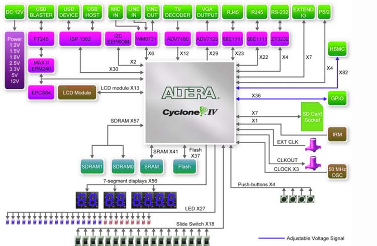
DE2-115 Board Block Diagram
The basic block diagram of the DE2-115 board is shown below. You can check out the datasheet for more info on the device.
Power up the DE2-115 Board
The DE2-115 board comes with a preloaded configuration bitstream to demonstrate some features of the board. This bitstream also allows users to see quickly if the board is working properly.
To power up the board, perform the following steps:
1. Connect the provided USB cable from the host computer to the USB Blaster connector on the DE2-115 board. For communication between the host and the DE2-115 board, it is necessary to install the Altera USB Blaster driver software. If this driver is not already installed on the host computer, it can be installed as explained in the tutorial “Getting Started with Altera's DE2-115 Board” (DE2-115 board datasheet) which is linked on the bottom of the page. This tutorial is available in the directory DE2_115_tutorials on the DE2-115 System CD.
2. Turn off the power by pressing the red ON/OFF switch before connecting the 12V adapter to the DE2-115 board.
3. Connect a VGA monitor to the VGA port on the DE2-115 board.
4. Connect your headset to the line-out audio port on the DE2-115 board.
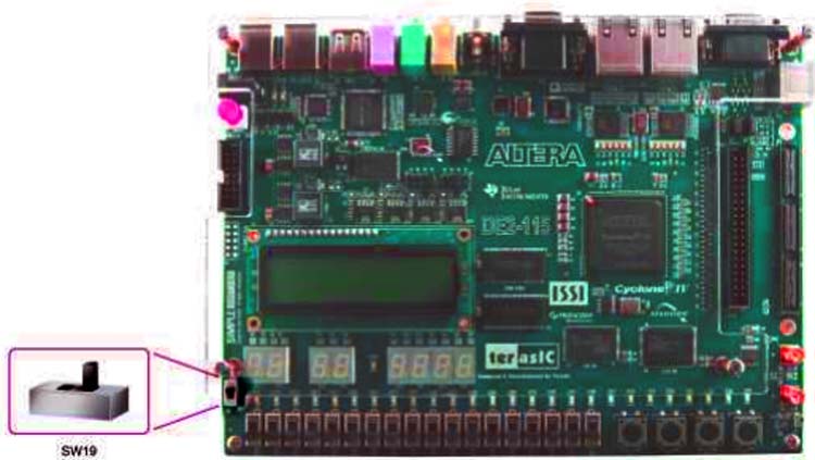
5. Turn the RUN/PROG switch (SW19) on the left edge of the DE2-115 board to the RUN position; the PROG position is used only for the AS Mode programming.
6. Recycle the power by turning the red power switch (on the DE2-115 board) OFF and ON again.
At this point you should observe the following:
- All user LEDs are flashing
- All 7-segment displays are cycling through the numbers 0 to F
- The LCD display shows “Welcome to the Altera DE2-115”
- The VGA monitor displays the image shown in Figure 2-4
- Set the slide switch SW17 to the DOWN position; you should hear a 1-kHz sound. Be careful of loud volume for avoiding any discomfort
- Set the slide switch SW17 to the UP position and connect the output of an audio player to the line-in connector on the DE2-115 board; on your speaker or headset you should hear the music played from the audio player (MP3, PC, iPod, or the like)
- You can also connect a microphone to the microphone-in connector on the DE2-115 board; your voice will be mixed with the music playing on the audio player.
The DE2-115 board comes with a Control Panel facility that allows users to access various components on the board from a host computer. The host computer communicates with the board through a USB connection. The facility can be used to verify the functionality of components on the board or be used as a debug tool while developing RTL code. This chapter first presents some basic functions of the Control Panel, then describes its structure in block diagram form, and finally describes its capabilities
JTAG Chain on DE2-115 Board
To use the JTAG interface for configuring an FPGA device, the JTAG chain on DE2-115 must form a close loop that allows the Quartus II programmer to detect the FPGA device. Shorting pin1 and pin2 on JP3 can disable the JTAG signals on the HSMC connector that will form a close JTAG loop chain on the DE2-115 board. To do that you need to flip the switch SW19 on the board to enable JTAG.
Applications
- high-speed search
- aerospace and defense
- medical electronics
- digital television
- consumer electronics
- industrial motor control
- scientific instruments
- cybersecurity systems, and wireless communications