USB Type-A (Female) Connector
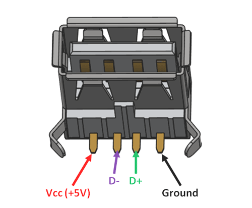
Pin Configuration
|
Pin No: |
Pin Name: |
Description |
|
1 |
Vcc |
This pin should be provided with +5V, through which the device is powered |
|
2 |
D- |
Differential pair D-, must be connected to D- of the host for data transfer |
|
3 |
D+ |
Differential pair D+, must be connected to D+ of the host fo data transfer |
|
4 |
Ground |
Connected to the ground pin of the host. |
Features
- Type-A USB 2.0 Plug (Female)
- Universal and secure USB protocol
- Its plug and play (Hot pluggable)
- Can be used to interface mouse and keyboards to uP/uC
- USB power supply: 100 to 500 mA
- Protocol supports robust error detection
Alternative USB plugs
micro-USB, USB Type-B, USB Type-C
Where to Use USB-A Jack
The term USB stands for Universal Serial Bus, as the name implies it is universal form of communication which is even now supported by all hardware and software that has USB host. This works through Asynchronous Serial Protocol, meaning there is no clock shared between the sender and receiver. Every device that we connect to USB port works though this protocol. If a Microcontroller or Microprocessor supports USB host, then we can connect any USB device like Keyboard, mouse, camera, printer, MP3 player, etc. to exchange information between this device and the host (uP or uC). It can also be used to transfer data between two Microcontrollers and Microprocessor, if you project requires you to do so. Few popular microcontrollers that support USB host are Arduino USB host, UMFT120DC, Arm Cortex M4, etc.
So if your project requires you to establish an USB connection, then this jack can be connected to the device and wired to your uP or uC.
How to use USB-A Jack
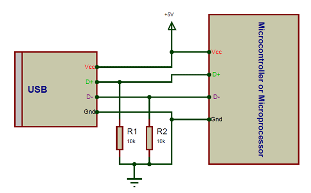
The USB Jack has only three pins and hence is relatively simple to use. Out of the four pin two pins (pin 1 and Pin 4) are used to provide the Vcc and Ground. The supply voltage of Vcc is +5V and is usually provided from the Microcontroller itself. The ground pin is connected to the ground of microcontroller.
The remaining two pins are the D+ and the D-. These pins should be connected to the D+ and D- pins of the host respectively. They also require a pull-down resistor of value 15K each for the data to transfer. A sample connection set-up is shown below.
Based on the microcontroller you are using there are a tons of library that are available to work with USB protocol, use one of them and you should be all set to use USB peripherals with your project.
Applications
- Interface Keyboard or mouse with MCU
- Serial Bus connections
- Portable and pluggable devices
- Small distance, high speed communication
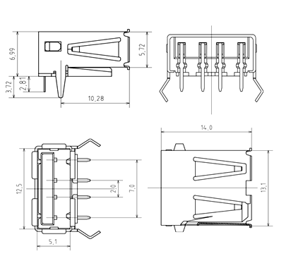
2D Model of USB-A Jack