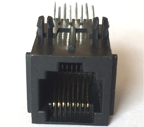
RJ45 8-Pin Connector
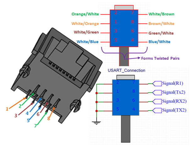
Pin Identification
|
No: |
Pin Number |
Pair |
Wire Color |
|
1 |
1 |
Pair 1 |
White with Orange |
|
2 |
8 |
Brown with White |
|
|
3 |
2 |
Pair 2 |
Orange with White |
|
4 |
7 |
White with Brown |
|
|
5 |
3 |
Pair 3 |
White with Green |
|
6 |
6 |
Green with White |
|
|
7 |
4 |
Pair 4 |
Blue with White |
|
8 |
5 |
White with Blue |
RJ45 Connector Specifications
- 8P8C RJ-45 Connector (8-pin connector)
- Through Hole PCB mount socket
- Compatible with all CAT and UDP cable
Related Materials
CAT Cables, USART modules, RS232 to TTL converters, RJ45 Modules
Other RJ45 Connector
Molex RJ45 Connector, RJ45 MagJack Breakout, Transceiver Board
Where to Use RJ45 Connectors
RJ45 is a type of communication protocol that is used for Ethernet and other long distance communications. In this type of communication, Data is transmitted between two electronics devices like Microcontrollers or Microprocessors over a very long distance without getting it lost. Normally communication protocols like SPI, USART, IIC will be used to transfer these data. These two devices are linked using a cable like CAT cables. The CAT cables are connected to the circuit through this RJ45 Connector. These connectors support any type of Ethernet cable like USP, CAT5e, CAT6, etc.
There are also many types of RJ45 connectors, but they all serve the same function other than the appearance and built quality. So if you are looking for a connector to communicate through RJ45 Protocol, then this connector might be the right choice for you.
How to use RJ45 Connector
The RJ45 connector has 8 pins as shown above. It is very important to select the appropriate pins for your data and ground to make the RJ45 protocol work efficiently. The main advantage of using RJ45 communication is that they are connected using CAT cables. These CAT cables are made up of twisted paired wires and the wires are housed inside a cable which can protect it from external noise. Since the wires are twisted in a pair of two, among these two wires one will be used to carry the signal or the data and the other will be a ground wire which will remove the noise from the data wire during high distance transmission.
A simple sample connection diagram for a USART connection with two RX and TX data lines is shown below:
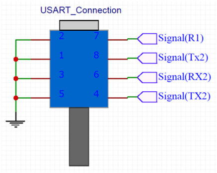
The data lines can be anything from USART, SPI or even IIC. Note that in every twisted pair one wire carries the data and the other is connected to ground. Other alternative methods for this protocol are the RS232 communication and the RS485 Communication protocol. These cables also support POE (Power over Ethernet) and hence can also carry power to the modules if required
Applications
- Commonly used in Ethernet Connection
- Transmit Data over Long distance
- Transmit data in noisy environment
- Long distance wired Connection
- Supports Power over Ethernet
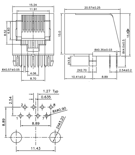
Dimensions of the module


Wrong pinout on the picture
Hi!
As far as I understand the upper right picture is wrong for this pinout.
It seems you took this pinout from the drawing below but that has contacts on the top side, please correct.
d;-)