MIL-DTL-83513 DB9 Serial Port Micro-D Connectors
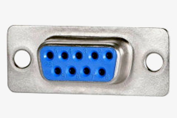
Micro-D Connectors are sub-miniature panel-type connectors with polarized shells. This type of connector use pin & socket machined contacts that are reliable for critical applications. With their versatile design, these high-performance connectors are used in a variety of applications where weight & size are critical factors. An example would be the blue port on the backside of the old motherboard which was used to connect serial devices.
These connectors are ideally suited for applications requiring extremely small, lightweight, and ruggedized solutions with higher density contact configurations.
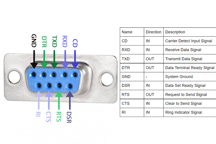
DB9 Micro-D Connector Pinout Configuration
|
DB9 Pin No |
Name |
Direction |
Description |
|
1 |
CD |
IN |
Carrier Detect Input Signal |
|
2 |
RXD |
IN |
Receive Data Signal |
|
3 |
TXD |
OUT |
Transmit Data Signal |
|
4 |
DTR |
OUT |
Data Terminal Ready Signal |
|
5 |
GND |
- |
System Ground |
|
6 |
DSR |
IN |
Data Set Ready Signal |
|
7 |
RTS |
OUT |
Request to Send Signal |
|
8 |
CTS |
IN |
Clear to Send Signal |
|
9 |
RI |
IN |
Ring Indicator Signal |
Features and Specification
- Standard Shell of Steel/Brass
- Multiple shell options in aluminium
- Wired pigtail, solder cup, right angle, condensed right angle, and straight PC tail options
- High-performance Cannon Twist Pin Contacts
- Copper Alloy Contact / Gold Platted Contact
- 3A Max Contact Current
- Tested Max Voltage is 600VAC
- Operating Temperature -55 to +125 Degrees C
- 500 Mating Cycles
Note: Complete technical details about this connector can be found in the DB9 Port Connector Datasheet given at the end of the page.
MIL-DTL-83513 Serial Port Connector Description
MIL-DTL-83513 series connectors are available in many different pin configurations ranging from 9 to 100 and can be used for military and aviation. But for the sake of simplicity, we are going to take the example of the DB9 port. Both Serial and Parallel Ports have been used since the beginning of the PC era and they mostly remained unchanged over the years. The RS-232 protocol was first introduced in the 60s that defines how the data is transferred bit by bit from a data terminal equipment such as a computer to an external terminal or any data communication equipment like mode or any other devices. The RS-232 is the common standard used in serial ports. It defines the electrical properties and the timing of signals, as well as the interpretation of signals. One of the original uses of the serial port was to use to transfer data between two PCs. Other than that, it was used in old modems and mouse.
Applications
- Military
- C4I
- Missiles
- Commercial Aerospace
- Avionics
- In-Flight Entertainment
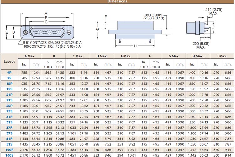
2D Model and Dimensions
Below is the 2D model of the Serial port connector along with its dimensions in inches(millimeters). The following information can be used to design the custom footprints and can be used for PCB designing and CAD modeling.