MIL-DTL-24308 DB25 Parallel Port Connector
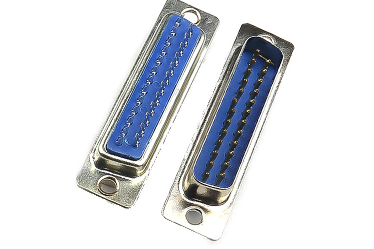
D-Sub connectors are sub-miniature panel-type connectors with polarized shells. These use pin & socket machined contacts that provide high reliability & density for the connectors. With their versatile design, these high-performance connectors are used in a variety of applications where weight & size are critical factors. An example would be the pink port on the backside of the old motherboard which was used to connect dot matrix printers.
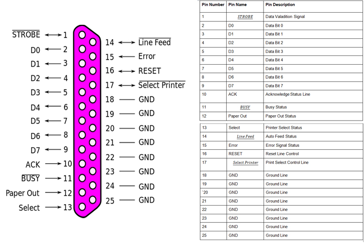
DB25 Port Connector Pinout Configuration
|
Pin Number |
Pin Name |
Pin Description |
|
1 |
STROBE |
Data Validation Signal |
|
2 |
D0 |
Data Bit 0 |
|
3 |
D1 |
Data Bit 1 |
|
4 |
D2 |
Data Bit 2 |
|
5 |
D3 |
Data Bit 3 |
|
6 |
D4 |
Data Bit 4 |
|
7 |
D5 |
Data Bit 5 |
|
8 |
D6 |
Data Bit 6 |
|
9 |
D7 |
Data Bit 7 |
|
10 |
ACK |
Acknowledge Status Line |
|
11 |
BUSY |
Busy Status |
|
12 |
Paper Out |
Paper Out Status |
|
13 |
Select |
Printer Select Status |
|
14 |
Line Feed |
Auto Feed Status |
|
15 |
Error |
Error Signal Status |
|
16 |
RESET |
Reset Line Control |
|
17 |
Select Printer |
Print Select Control Line |
|
18 |
GND |
Ground Line |
|
19 |
GND |
Ground Line |
|
`20 |
GND |
Ground Line |
|
21 |
GND |
Ground Line |
|
22 |
GND |
Ground Line |
|
23 |
GND |
Ground Line |
|
24 |
GND |
Ground Line |
|
25 |
GND |
Ground Line |
Features and Specification
- Standard Shell of Steel/Brass
- Glass–Filled Polyester UL 94-0 Insulator
- Copper Alloy Contact / Gold Platted Contact
- 7.5A Max Contact Current
- Tested Max Voltage is 1000 Vrms
- Insulation Resistance >5000 M ohms
- Contact Resistance 7.5m Ohms
Note: Complete technical details about this connector can be found in the DB25 Port Connector datasheet at the end of the page.
MIL-DTL-24308 Parallel Port Connector Description
The parallel port was used in the computer since the beginning of the PC era and it mostly remained unchanged over the years. This was first introduced when IBM came up with its PC, they had a discussion with the most prominent printer manufacturer at the time known as Centronics, and they came up with the control signal line necessary for the signals to control the printer with the PC, and ever since this design has become the standard design for many printer manufacturers.
When IBM first constructed a PC they opted to go with the DB25 or D-Sub connector as it was less bulky than a printer 36-port connector. The printer manufacturers always use a 36-pin connector and the PC has a 25-pin D-sub connector and to connect the printer to the PC you need this special adapter cable which is known as a printer cable. As the interfacing process was easy the parallel port become one of the most commonly used ports for DIY applications, even now you can program an AVR microcontroller with a parallel port connector and it can be used for basic home automation projects. This port can handle and input up to 9-bits and output of 12-bits at any one given time, thus requiring minimal external circuitry to do simpler tasks. The port is composed of 4 control lines, 5 status lines, and 8 data lines. It’s can be commonly found on the back of your PC as a D-Type 25 Pin female connector colored in pink.
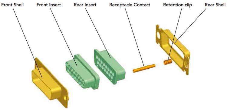
Assembly Process of Parallel Port Connector
The assembly process of this DB-25 connector is shown below as referred to in the datasheet.
Applications
- Military
- C4I
- Missiles
- Commercial Aerospace
- Avionics
- In-Flight Entertainment
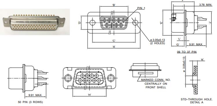
2D Model and Dimensions
Below is the 2D model of the port connector along with its dimensions in inches(millimeters). The following information can be used to design the custom footprints and can be used for PCB designing and CAD modeling.